DESCRIPTION The illumination of the low beam headlights is controlled by the main body ECU (multiplex network body ECU). When the headlights are turned on, the main body ECU (multiplex network body ECU) receives a signal from the headlight assembly and detects the illumination condition of the low beam headlights.
HINT: DTC B2430 and B2431 are not output if 20 seconds have not elapsed since the ignition switch was turned on. WIRING DIAGRAM 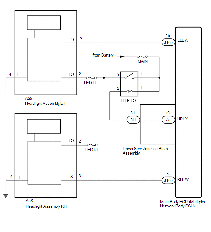
CAUTION / NOTICE / HINT NOTICE: Inspect the fuses for circuits related to this system before performing the following procedure. PROCEDURE
(a) Clear the DTCs. Click here (b) Check for DTCs. Click here OK: DTC B2430 and B2431 are not output.
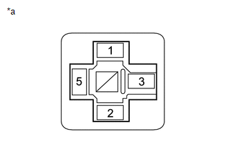
(a) Remove the headlight relay (H-LP LO) from the engine room relay block and junction block. (b) Inspect the headlight relay (H-LP LO). Click here
(b) Measure the voltage according to the value(s) in the table below. Standard Voltage:
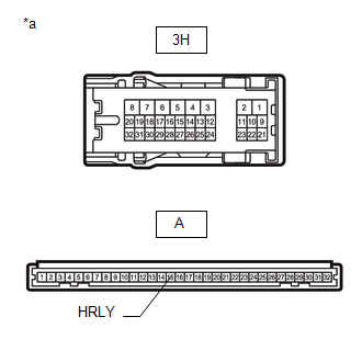
(a) Remove the headlight relay (H-LP LO) from the engine room relay block and junction block. (b) Disconnect the 3H driver side junction block assembly connector. (c) Disconnect the A59 headlight assembly LH connector. (d) Disconnect the A58 headlight assembly RH connector. (e) Measure the resistance according to the value(s) in the table below. Standard Resistance:
(b) Remove the main body ECU (multiplex network body ECU) from the driver side junction block assembly. Click here (c) Measure the resistance according to the value(s) in the table below. Standard Resistance:
(a) Remove the headlight relay (H-LP LO) from the engine room relay block and junction block. (b) Disconnect the A59 headlight assembly LH connector. (c) Measure the resistance according to the value(s) in the table below. Standard Resistance:
(a) Disconnect the A59 headlight assembly LH connector. (b) Disconnect the J165 main body ECU (multiplex network body ECU) connector. (c) Measure the resistance according to the value(s) in the table below. Standard Resistance:
(a) Temporarily replace the headlight assembly LH with a new or normally functioning one. Click here (b) Clear the DTCs. Click here (c) Check for DTCs. Click here OK: DTC B2430 is not output.
(a) Remove the headlight relay (H-LP LO) from the engine room relay block and junction block. (b) Disconnect the A58 headlight assembly RH connector. (c) Measure the resistance according to the value(s) in the table below. Standard Resistance:
(a) Disconnect the A58 headlight assembly RH connector. (b) Disconnect the J165 main body ECU (multiplex network body ECU) connector. (c) Measure the resistance according to the value(s) in the table below. Standard Resistance:
(a) Temporarily replace the headlight assembly RH with a new or normally functioning one. Click here (b) Clear the DTCs. Click here (c) Check for DTCs. Click here OK: DTC B2431 is not output.
|
Toyota Tundra Service Manual > Steering Pad: Removal
REMOVAL PROCEDURE 1. PRECAUTION CAUTION: Be sure to read Precaution thoroughly before servicing (See page ). NOTICE: After turning the ignition switch off, waiting time may be required before disconnecting the cable from the negative (-) battery terminal. Therefore, make sure to read the disconnecti ...