DESCRIPTION This circuit detects the ignition switch ON or off condition, and sends it to the main body ECU (multiplex network body ECU). WIRING DIAGRAM 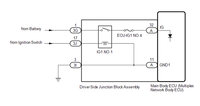
CAUTION / NOTICE / HINT NOTICE: Inspect the fuses for circuits related to this system before performing the following procedure. PROCEDURE
(a) Read the Data List according to the display on the Techstream. Click here
OK: Normal conditions listed above are displayed.
(a) Disconnect the driver side junction block assembly connectors. 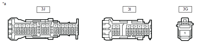
(b) Measure the voltage according to the value(s) in the table below. Standard Voltage:
(c) Measure the resistance according to the value(s) in the table below. Standard Resistance:
(a) Remove the driver side junction block assembly. Click here 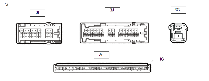
(b) Remove the main body ECU (multiplex network body ECU) from the driver side junction block assembly. Click here (c) Measure the resistance according to the value(s) in the table below. Standard Resistance:
|
Toyota Tundra Service Manual > Air Conditioning System(for Automatic Air Conditioning System): Room Temperature Sensor Circuit (B1411/11)
DESCRIPTION The room temperature sensor is installed in the instrument panel to detect the room temperature and control the heater and air conditioner "AUTO" mode. The resistance of the room temperature sensor changes in accordance with the room temperature. As the temperature decreases, t ...


