DESCRIPTION The main body ECU (multiplex network body ECU) controls the operation of the following lights:
WIRING DIAGRAM 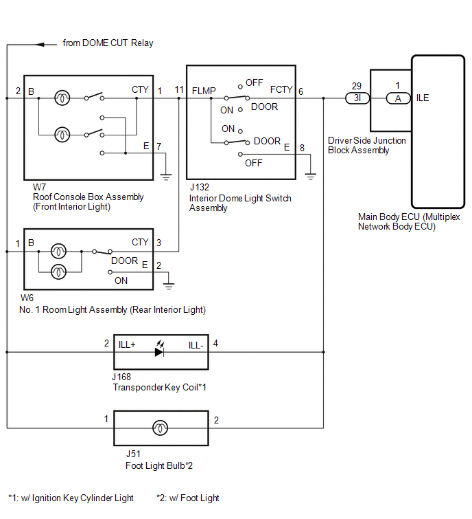
CAUTION / NOTICE / HINT NOTICE: Inspect the bulbs for circuits related to this system before performing the following procedure. PROCEDURE
(a) Using the Techstream, perform the Active Test. Click here
OK: All of the interior lights turn on when ON is selected.
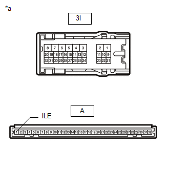
(a) Disconnect the 3I driver side junction block assembly connector. (b) Disconnect the J132 interior dome light switch assembly connector. (c) Disconnect the J168 transponder key coil connector.*1 (d) Disconnect the J51 foot light bulb connector.*2 (e) Measure the resistance according to the value(s) in the table below. Standard Resistance:
(b) Remove the main body ECU (multiplex network body ECU) from the driver side junction block assembly. Click here (c) Measure the resistance according to the value(s) in the table below. Standard Resistance:
|
Toyota Tundra Service Manual > Navigation System: Data Signal Circuit between Navigation Receiver Assembly and Extension Module
DESCRIPTION The stereo component tuner assembly sends the sound data signal or image data signal from a device to the navigation receiver assembly via this circuit. WIRING DIAGRAM CAUTION / NOTICE / HINT NOTICE: After replacing the stereo component tuner assembly of vehicles subscribed to pay-type s ...