Toyota Tundra Service Manual: Turn Signal Switch Circuit

DESCRIPTION

The combination meter assembly receives the turn signal switch information and controls the turn signal lights.

WIRING DIAGRAM

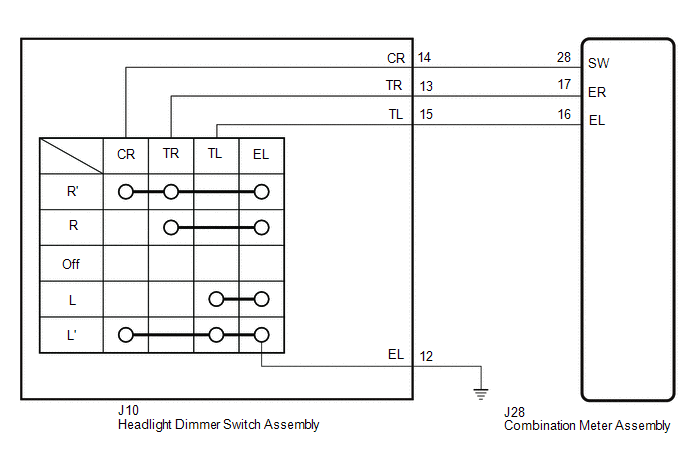
CAUTION / NOTICE / HINT

NOTICE:

When replacing the combination meter assembly, always replace it with a new one. If a combination meter assembly which was installed to another vehicle is used, the information stored in it will not match the information from the vehicle and a DTC may be stored.

PROCEDURE

1.

READ VALUE USING TECHSTREAM

(a) Using the Techstream, read the Data List.

Click here

Combination Meter

Tester Display

Measurement Item / Range

Normal Condition

Diagnostic Note

Turn Signal Switch (Right)

Turn signal switch (right) signal / OFF or ON

OFF: Turn signal switch (right) off

ON: Turn signal switch (right) on

-

Turn Signal Switch (Left)

Turn signal switch (left) signal / OFF or ON

OFF: Turn signal switch (left) off

ON: Turn signal switch (left) on

-

Turn Switch Signal (Full Turn)

Turn signal switch signal / OFF or ON

OFF: Turn signal switch off

OFF: Turn signal switch on (Full Turn)

Displays for both right and left turns.

OK:

Normal condition listed above are displayed.

OK

PROCEED TO NEXT SUSPECTED AREA SHOWN IN PROBLEM SYMPTOMS TABLE

NG

2.

INSPECT HEADLIGHT DIMMER SWITCH ASSEMBLY

(a) Remove the headlight dimmer switch assembly.

Click here

(b) Inspect the headlight dimmer switch assembly.

Click here

NG

REPLACE HEADLIGHT DIMMER SWITCH ASSEMBLY

OK

3.

CHECK HARNESS AND CONNECTOR (HEADLIGHT DIMMER SWITCH ASSEMBLY - COMBINATION METER ASSEMBLY AND BODY GROUND)

(a) Disconnect the J10 headlight dimmer switch assembly connector.

(b) Disconnect the J28 combination meter assembly connector.

(c) Measure the resistance according to the value(s) in the table below.

Standard Resistance:

Tester Connection

Condition

Specified Condition

J10-14 (CR) - J28-28 (SW)

Always

Below 1 Ω

J10-13 (TR) - J28-17 (ER)

Always

Below 1 Ω

J10-15 (TL) - J28-16 (EL)

Always

Below 1 Ω

J10-12 (EL) - Body ground

Always

Below 1 Ω

J10-14 (CR) or J28-28 (SW) - Body ground

Always

10 kΩ or higher

J10-13 (TR) or J28-17 (ER) - Body ground

Always

10 kΩ or higher

J10-15 (TL) or J28-16 (EL) - Body ground

Always

10 kΩ or higher

OK

REPLACE COMBINATION METER ASSEMBLY

NG

REPAIR OR REPLACE HARNESS OR CONNECTOR

    Terminals Of Ecu

    Lost Communication With Image Processing Module "A" (U023A)

    See More:

    Toyota Tundra Service Manual > Front Power Seat Control System(w/ Memory): One or more Power Seat Motors do not Operate
    DESCRIPTION When a signal is input into the position control ECU and switch assembly, the ECU manages the signals received from the power seat switches, and operates each motors. If the position control ECU and switch assembly receives more than 2 motor operation signals, the motor is stopped. Manua ...

    Toyota Tundra Owners Manual

    Toyota Tundra Service Manual

    © 2024 Copyright www.ttundra.com
    0.0106