Components COMPONENTS ILLUSTRATION 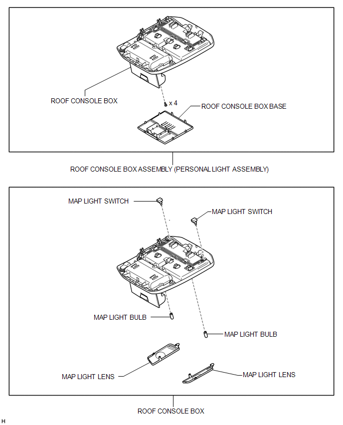
Disassembly DISASSEMBLY PROCEDURE 1. REMOVE MAP LIGHT BULB 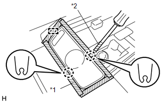
HINT: Use the same procedure for both map light bulbs. (a) Put protective tape around the map light lens. Text in Illustration
(b) Using a screwdriver, detach the 2 claws and guide and remove the map light lens. HINT: Tape the screwdriver tip before use. Text in Illustration
2. REMOVE MAP LIGHT SWITCH 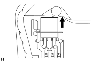
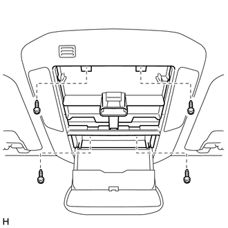
HINT: Use the same procedure for both map light switches. (a) Remove the map light switch from the roof console box. Installation INSTALLATION PROCEDURE 1. INSTALL ROOF CONSOLE BOX ASSEMBLY (PERSONAL LIGHT ASSEMBLY) (a) Connect the connector. (b) Using a T20 "TORX" socket wrench, install the roof console box assembly (personal light assembly) with the 4 screws. (c) Attach the 8 claws to install the roof console box base. Reassembly REASSEMBLY PROCEDURE 1. INSTALL MAP LIGHT SWITCH 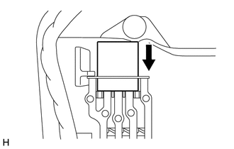
HINT: Use the same procedure for both map light switches. (a) Install the map light switch to the roof console box. 2. INSTALL MAP LIGHT BULB HINT: Use the same procedure for both map light bulbs. (a) Install the map light bulb to the roof console box. (b) Attach the 2 claws and guide to install the map light lens. Removal REMOVAL PROCEDURE 1. REMOVE ROOF CONSOLE BOX ASSEMBLY (PERSONAL LIGHT ASSEMBLY) 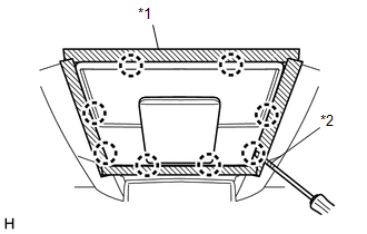
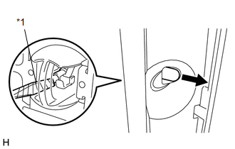
(a) Put protective tape around the roof console box base. Text in Illustration
(b) Using a screwdriver, detach the 8 claws and remove the roof console box base. HINT: Tape the screwdriver tip before use. Text in Illustration
(d) Disconnect the connector and remove the roof console box assembly (personal light assembly). |
Toyota Tundra Service Manual > Center Power Outlet Socket(for Floor Shift Type): Removal
REMOVAL PROCEDURE 1. REMOVE UPPER REAR CONSOLE PANEL SUB-ASSEMBLY 2. REMOVE UPPER CONSOLE PANEL SUB-ASSEMBLY 3. REMOVE CONSOLE BOX BEZEL (a) Disconnect the connector. (b) Using a screwdriver, detach the 5 claws and remove the console box bezel. HINT: Tape the screwdriver tip before use. Text in Illu ...