Components COMPONENTS ILLUSTRATION 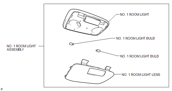
Disassembly DISASSEMBLY PROCEDURE 1. REMOVE NO. 1 ROOM LIGHT BULB 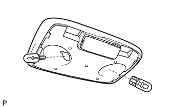
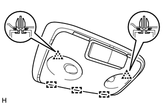
(a) Remove the 2 No. 1 room light bulbs from the No. 1 room light. Installation INSTALLATION PROCEDURE 1. INSTALL NO. 1 ROOM LIGHT ASSEMBLY (a) Attach the 3 guides and 2 clips to install the No. 1 room light assembly. (b) Attach the 2 guides and 4 claws to install the No. 1 room light lens. Reassembly REASSEMBLY PROCEDURE 1. INSTALL NO. 1 ROOM LIGHT BULB (a) Install the 2 No. 1 room light bulbs to the No. 1 room light. Removal REMOVAL PROCEDURE 1. REMOVE NO. 1 ROOM LIGHT ASSEMBLY 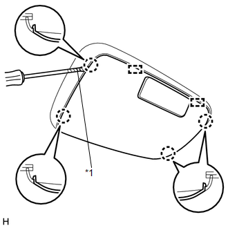
(a) Using a screwdriver, detach the 4 claws and 2 guides and remove the No. 1 room light lens. Text in Illustration
|
Toyota Tundra Service Manual > Sfi System: Oxygen (A/F) Sensor Heater Control Circuit Low (Bank 1 Sensor 1) (P0031,P0032,P0051,P0052,P101D,P103D)
DESCRIPTION Refer to DTC P2195 (See page ). HINT: Although the DTC titles say oxygen sensor, these DTCs relate to the Air-Fuel Ratio (A/F) sensor. Sensor 1 refers to the sensor mounted in front of the Three-Way Catalytic Converter (TWC) and located near the engine assembly. When one of these DTCs is ...