DESCRIPTION
|
DTC Code
|
DTC Detection Condition
|
Trouble Area
|
|
B1507
|
Open in turn signal light circuit.
|
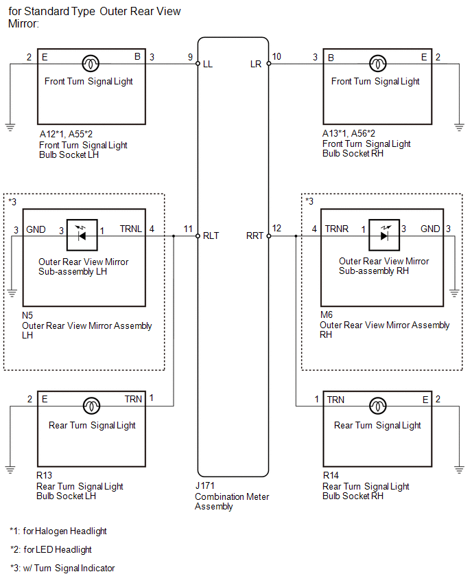
- for Standard Type Outer Rear View Mirror:
- Harness or connector
- Front turn signal light bulb socket
- Rear turn signal light bulb socket
- Outer rear view mirror assembly (w/ Turn Signal Indicator)
- Outer rear view mirror sub-assembly (w/ Turn Signal Indicator)
- Combination meter asssembly
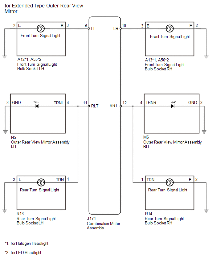
- for Extended Type Outer Rear View Mirror:
- Harness or connector
- Front turn signal light bulb socket
- Rear turn signal light bulb socket
- Outer rear view mirror assembly
- Combination meter asssembly
|
|
B1508
|
Short in turn signal light circuit or hazard warning light circuit.
|
- for Standard Type Outer Rear View Mirror:
- Harness or connector
- Front turn signal light bulb socket
- Rear turn signal light bulb socket
- Outer rear view mirror assembly (w/ Turn Signal Indicator)
- Outer rear view mirror sub-assembly (w/ Turn Signal Indicator)
- Combination meter asssembly
- for Extended Type Outer Rear View Mirror:
- Harness or connector
- Front turn signal light bulb socket
- Rear turn signal light bulb socket
- Outer rear view mirror assembly
- Combination meter asssembly
|
WIRING DIAGRAM
CAUTION / NOTICE / HINT
NOTICE:
Inspect the bulbs for circuits related to this system before performing the following
inspection procedure.
PROCEDURE
(a) Clear the DTCs.
Click here 
(b) Recheck for DTCs and check that no DTCs are output.
Click here
OK:
B1507 and B1508 are not output.
| OK |
 |
USE SIMULATION METHOD TO CHECK
|
| NG |

|
|
(a) Check the vehicle type.
|
Result
|
Proceed to
|
|
for Standard Type Outer Rear View Mirror
|
A
|
|
for Extended Type Outer Rear View Mirror
|
B
|
| B |
|
GO TO STEP 22
|
| A |
|
|
|
(a) Inspect the illumination of each turn signal light.
|
Result
|
Proceed to
|
|
LH side turn signal light does not illuminate.
|
A
|
|
RH side turn signal light does not illuminate.
|
B
|
| B |
|
GO TO STEP 13
|
| A |
|
|
|
|
4.
|
CHECK TURN SIGNAL LIGHTS (LH SIDE)
|
(a) Turn the ignition switch to ON.
(b) Set the headlight dimmer switch assembly to the left turn switch position.
(c) Check the operation of the turn signal lights (LH side).
|
Result
|
Proceed to
|
|
Front turn signal light (LH side) does not blink.
|
A
|
|
Side turn signal indicator (LH side) does not blink. (w/ Turn Signal
Indicator)
|
B
|
|
Rear turn signal light (LH side) does not blink.
|
C
|
|
Side turn signal indicator and rear turn signal light (LH side) does
not blink. (w/ Turn Signal Indicator)
|
D
|
| B |
|
GO TO STEP 7
|
| C |
|
GO TO STEP 10
|
| D |
|
GO TO STEP 12
|
| A |
|
|
|
|
5.
|
CHECK HARNESS AND CONNECTOR (FRONT TURN SIGNAL LIGHT BULB SOCKET LH -
COMBINATION METER ASSEMBLY AND BODY GROUND)
|
(a) for Halogen Headlight:
(1) Disconnect the A12 front turn signal light bulb socket LH connector.
(2) Disconnect the J171 combination meter assembly connector.
(3) Measure the resistance according to the value(s) in the table below.
Standard Resistance (Check for Open):
|
Tester Connection
|
Condition
|
Specified Condition
|
|
A12-3 (B) - J171-9 (LL)
|
Always
|
Below 1 Ω
|
|
A12-2 (E) - Body ground
|
Always
|
Below 1 Ω
|
Standard Resistance (Check for Short):
|
Tester Connection
|
Condition
|
Specified Condition
|
|
A12-3 (B) - Body ground
|
Always
|
10 kΩ or higher
|
(b) for LED Headlight:
(1) Disconnect the A55 front turn signal light bulb socket LH connector.
(2) Disconnect the J171 combination meter assembly connector.
(3) Measure the resistance according to the value(s) in the table below.
Standard Resistance (Check for Open):
|
Tester Connection
|
Condition
|
Specified Condition
|
|
A55-3 (B) - J171-9 (LL)
|
Always
|
Below 1 Ω
|
|
A55-2 (E) - Body ground
|
Always
|
Below 1 Ω
|
Standard Resistance (Check for Short):
|
Tester Connection
|
Condition
|
Specified Condition
|
|
A55-3 (B) - Body ground
|
Always
|
10 kΩ or higher
|
| NG |
|
REPAIR OR REPLACE HARNESS OR CONNECTOR
|
| OK |
|
|
|
|
6.
|
INSPECT FRONT TURN SIGNAL LIGHT BULB SOCKET LH
|
(a) Remove the front turn signal light bulb socket LH.
for Halogen Headlight: Click here
for LED Headlight: Click here
|
(b) Measure the resistance according to the value(s) in the table below.
Standard Resistance (Check for Open):
|
Tester Connection
|
Condition
|
Specified Condition
|
|
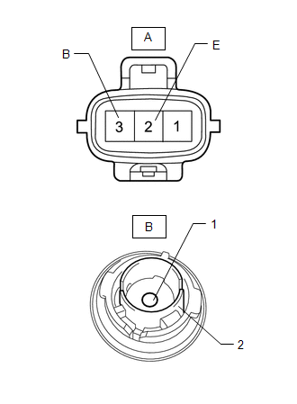
A-3 (B) - B-1
|
Always
|
Below 1 Ω
|
|
A-2 (E) - B-2
|
Always
|
Below 1 Ω
|
Standard Resistance (Check for Short):
|
Tester Connection
|
Condition
|
Specified Condition
|
|
A-3 (B) - A-2 (E)
|
Always
|
10 kΩ or higher
|
|
|
| OK |
|
REPLACE COMBINATION METER ASSEMBLY
|
| NG |
|
REPLACE FRONT TURN SIGNAL LIGHT BULB SOCKET LH
|
|
7.
|
CHECK HARNESS AND CONNECTOR (OUTER REAR VIEW MIRROR ASSEMBLY LH - COMBINATION
METER ASSEMBLY AND BODY GROUND)
|
(a) Disconnect the N5 outer rear view mirror assembly LH connector.
(b) Disconnect the J171 combination meter assembly connector.
(c) Measure the resistance according to the value(s) in the table below.
Standard Resistance (Check for Open):
|
Tester Connection
|
Condition
|
Specified Condition
|
|
N5-4 (TRNL) - J171-11 (RLT)
|
Always
|
Below 1 Ω
|
|
N5-3 (GND) - Body ground
|
Always
|
Below 1 Ω
|
Standard Resistance (Check for Short):
|
Tester Connection
|
Condition
|
Specified Condition
|
|
N5-4 (TRNL) - Body ground
|
Always
|
10 kΩ or higher
|
| NG |
|
REPAIR OR REPLACE HARNESS OR CONNECTOR
|
| OK |
|
|
|
|
8.
|
INSPECT OUTER REAR VIEW MIRROR ASSEMBLY LH
|
(a) Remove the outer rear view mirror assembly LH.
Click here
(b) Inspect the outer rear view mirror assembly LH.
Click here
| OK |
|
REPLACE COMBINATION METER ASSEMBLY
|
| NG |
|
|
|
|
9.
|
INSPECT OUTER REAR VIEW MIRROR SUB-ASSEMBLY LH
|
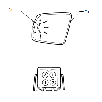
(a) Remove the outer rear view mirror sub-assembly LH.
Click here
|
(b) Apply battery voltage and check the operation of the turn signal
indicator.
OK:
|
Battery Connection
|
Specified Condition
|
|
Positive (+) → 1
Negative (-) → 3
|
Turn signal indicator illuminates
|
|
|
|
*a
|
Turn Signal Indicator
|
|
*b
|
Outer Rear View Mirror Sub-assembly LH
|
|
|
| OK |
|
REPLACE OUTER REAR VIEW MIRROR ASSEMBLY LH
|
| NG |
|
REPLACE OUTER REAR VIEW MIRROR SUB-ASSEMBLY LH
|
|
10.
|
CHECK HARNESS AND CONNECTOR (REAR TURN SIGNAL LIGHT BULB SOCKET LH -
COMBINATION METER ASSEMBLY AND BODY GROUND)
|
(a) Disconnect the R13 rear turn signal light bulb socket LH connector.
(b) Disconnect the J171 combination meter assembly connector.
(c) Measure the resistance according to the value(s) in the table below.
Standard Resistance (Check for Open):
|
Tester Connection
|
Condition
|
Specified Condition
|
|
R13-1 (TRN) - J171-11 (RLT)
|
Always
|
Below 1 Ω
|
|
R13-2 (E) - Body ground
|
Always
|
Below 1 Ω
|
Standard Resistance (Check for Short):
|
Tester Connection
|
Condition
|
Specified Condition
|
|
R13-1 (TRN) - Body ground
|
Always
|
10 kΩ or higher
|
| NG |
|
REPAIR OR REPLACE HARNESS OR CONNECTOR
|
| OK |
|
|
|
|
11.
|
INSPECT REAR TURN SIGNAL LIGHT BULB SOCKET LH
|
(a) Remove the rear turn signal light bulb socket LH.
Click here
|
(b) Measure the resistance according to the value(s) in the table below.
Standard Resistance (Check for Open):
|
Tester Connection
|
Condition
|
Specified Condition
|
|
A-1 (TRN) - B-1
|
Always
|
Below 1 Ω
|
|
A-2 (E) - B-2
|
Always
|
Below 1 Ω
|
Standard Resistance (Check for Short):
|
Tester Connection
|
Condition
|
Specified Condition
|
|
A-1 (TRN) - A-2 (E)
|
Always
|
10 kΩ or higher
|
|
|
| OK |
|
REPLACE COMBINATION METER ASSEMBLY
|
| NG |
|
REPLACE REAR TURN SIGNAL LIGHT BULB SOCKET LH
|
|
12.
|
CHECK HARNESS AND CONNECTOR (OUTER REAR VIEW MIRROR ASSEMBLY LH - COMBINATION
METER ASSEMBLY AND BODY GROUND)
|
(a) Disconnect the N5 outer rear view mirror assembly LH connector.
(b) Disconnect the J171 combination meter assembly connector.
(c) Measure the resistance according to the value(s) in the table below.
Standard Resistance (Check for Open):
|
Tester Connection
|
Condition
|
Specified Condition
|
|
N5-4 (TRNL) - J171-11 (RLT)
|
Always
|
Below 1 Ω
|
|
N5-3 (GND) - Body ground
|
Always
|
Below 1 Ω
|
Standard Resistance (Check for Short):
|
Tester Connection
|
Condition
|
Specified Condition
|
|
N5-4 (TRNL) - Body ground
|
Always
|
10 kΩ or higher
|
| OK |
|
REPLACE COMBINATION METER ASSEMBLY
|
| NG |
|
REPAIR OR REPLACE HARNESS OR CONNECTOR
|
|
13.
|
CHECK TURN SIGNAL LIGHTS (RH SIDE)
|
(a) Turn the ignition switch to ON.
(b) Set the headlight dimmer switch assembly to the right turn switch position.
(c) Check the operation of the turn signal lights (RH side).
|
Result
|
Proceed to
|
|
Front turn signal light (RH side) does not blink.
|
A
|
|
Side turn signal indicator (RH side) does not blink. (w/ Turn Signal
Indicator)
|
B
|
|
Rear turn signal light (RH side) does not blink.
|
C
|
|
Side turn signal indicator and rear turn signal light (RH side) does
not blink. (w/ Turn Signal Indicator)
|
D
|
| B |
|
GO TO STEP 16
|
| C |
|
GO TO STEP 19
|
| D |
|
GO TO STEP 21
|
| A |
|
|
|
|
14.
|
CHECK HARNESS AND CONNECTOR (FRONT TURN SIGNAL LIGHT BULB SOCKET RH -
COMBINATION METER ASSEMBLY AND BODY GROUND)
|
(a) for Halogen Headlight:
(1) Disconnect the A13 front turn signal light bulb socket RH connector.
(2) Disconnect the J171 combination meter assembly connector.
(3) Measure the resistance according to the value(s) in the table below.
Standard Resistance (Check for Open):
|
Tester Connection
|
Condition
|
Specified Condition
|
|
A13-3 (B) - J171-10 (LR)
|
Always
|
Below 1 Ω
|
|
A13-2 (E) - Body ground
|
Always
|
Below 1 Ω
|
Standard Resistance (Check for Short):
|
Tester Connection
|
Condition
|
Specified Condition
|
|
A13-3 (B) - Body ground
|
Always
|
10 kΩ or higher
|
(b) for LED Headlight:
(1) Disconnect the A56 front turn signal light bulb socket RH connector.
(2) Disconnect the J171 combination meter assembly connector.
(3) Measure the resistance according to the value(s) in the table below.
Standard Resistance (Check for Open):
|
Tester Connection
|
Condition
|
Specified Condition
|
|
A56-3 (B) - J171-10 (LR)
|
Always
|
Below 1 Ω
|
|
A56-2 (E) - Body ground
|
Always
|
Below 1 Ω
|
Standard Resistance (Check for Short):
|
Tester Connection
|
Condition
|
Specified Condition
|
|
A56-3 (B) - Body ground
|
Always
|
10 kΩ or higher
|
| NG |
|
REPAIR OR REPLACE HARNESS OR CONNECTOR
|
| OK |
|
|
|
|
15.
|
INSPECT FRONT TURN SIGNAL LIGHT BULB SOCKET RH
|
(a) Remove the front turn signal light bulb socket RH.
for Halogen Headlight: Click here
for LED Headlight: Click here
|
(b) Measure the resistance according to the value(s) in the table below.
Standard Resistance (Check for Open):
|
Tester Connection
|
Condition
|
Specified Condition
|
|
A-3 (B) - B-1
|
Always
|
Below 1 Ω
|
|
A-2 (E) - B-2
|
Always
|
Below 1 Ω
|
Standard Resistance (Check for Short):
|
Tester Connection
|
Condition
|
Specified Condition
|
|
A-3 (B) - A-2 (E)
|
Always
|
10 kΩ or higher
|
|
|
| OK |
|
REPLACE COMBINATION METER ASSEMBLY
|
| NG |
|
REPLACE FRONT TURN SIGNAL LIGHT BULB SOCKET RH
|
|
16.
|
CHECK HARNESS AND CONNECTOR (OUTER REAR VIEW MIRROR ASSEMBLY RH - COMBINATION
METER ASSEMBLY AND BODY GROUND)
|
(a) Disconnect the M6 outer rear view mirror assembly RH connector.
(b) Disconnect the J171 combination meter assembly connector.
(c) Measure the resistance according to the value(s) in the table below.
Standard Resistance (Check for Open):
|
Tester Connection
|
Condition
|
Specified Condition
|
|
M6-4 (TRNR) - J171-12 (RRT)
|
Always
|
Below 1 Ω
|
|
M6-3 (GND) - Body ground
|
Always
|
Below 1 Ω
|
Standard Resistance (Check for Short):
|
Tester Connection
|
Condition
|
Specified Condition
|
|
M6-4 (TRNR) - Body ground
|
Always
|
10 kΩ or higher
|
| NG |
|
REPAIR OR REPLACE HARNESS OR CONNECTOR
|
| OK |
|
|
|
|
17.
|
INSPECT OUTER REAR VIEW MIRROR ASSEMBLY RH
|
(a) Remove the outer rear view mirror assembly RH.
Click here
(b) Inspect the outer rear view mirror assembly RH.
Click here
| OK |
|
REPLACE COMBINATION METER ASSEMBLY
|
| NG |
|
|
|
|
18.
|
INSPECT OUTER REAR VIEW MIRROR SUB-ASSEMBLY RH
|
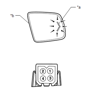
(a) Remove the outer rear view mirror sub-assembly RH.
Click here
|
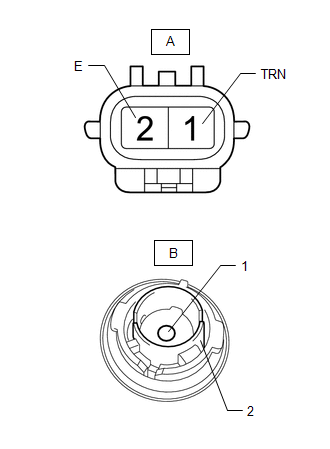
(b) Apply battery voltage and check the operation of the turn signal
indicator.
OK:
|
Battery Connection
|
Specified Condition
|
|
Positive (+) → 1
Negative (-) → 3
|
Turn signal indicator illuminates
|
|
|
|
*a
|
Turn Signal Indicator
|
|
*b
|
Outer Rear View Mirror Sub-assembly RH
|
|
|
| OK |
|
REPLACE OUTER REAR VIEW MIRROR ASSEMBLY RH
|
| NG |
|
REPLACE OUTER REAR VIEW MIRROR SUB-ASSEMBLY RH
|
|
19.
|
CHECK HARNESS AND CONNECTOR (REAR TURN SIGNAL LIGHT BULB SOCKET RH -
COMBINATION METER ASSEMBLY AND BODY GROUND)
|
(a) Disconnect the R14 rear turn signal light bulb socket RH connector.
(b) Disconnect the J171 combination meter assembly connector.
(c) Measure the resistance according to the value(s) in the table below.
Standard Resistance (Check for Open):
|
Tester Connection
|
Condition
|
Specified Condition
|
|
R14-1 (TRN) - J171-12 (RRT)
|
Always
|
Below 1 Ω
|
|
R14-2 (E) - Body ground
|
Always
|
Below 1 Ω
|
Standard Resistance (Check for Short):
|
Tester Connection
|
Condition
|
Specified Condition
|
|
R14-1 (TRN) - Body ground
|
Always
|
10 kΩ or higher
|
| NG |
|
REPAIR OR REPLACE HARNESS OR CONNECTOR
|
| OK |
|
|
|
|
20.
|
INSPECT REAR TURN SIGNAL LIGHT BULB SOCKET RH
|
(a) Remove the rear turn signal light bulb socket RH.
Click here
|
(b) Measure the resistance according to the value(s) in the table below.
Standard Resistance (Check for Open):
|
Tester Connection
|
Condition
|
Specified Condition
|
|
A-1 (TRN) - B-1
|
Always
|
Below 1 Ω
|
|
A-2 (E) - B-2
|
Always
|
Below 1 Ω
|
Standard Resistance (Check for Short):
|
Tester Connection
|
Condition
|
Specified Condition
|
|
A-1 (TRN) - A-2 (E)
|
Always
|
10 kΩ or higher
|
|
|
| OK |
|
REPLACE COMBINATION METER ASSEMBLY
|
| NG |
|
REPLACE REAR TURN SIGNAL LIGHT BULB SOCKET RH
|
|
21.
|
CHECK HARNESS AND CONNECTOR (OUTER REAR VIEW MIRROR ASSEMBLY RH - COMBINATION
METER ASSEMBLY AND BODY GROUND)
|
(a) Disconnect the M6 outer rear view mirror assembly RH connector.
(b) Disconnect the J171 combination meter assembly connector.
(c) Measure the resistance according to the value(s) in the table below.
Standard Resistance (Check for Open):
|
Tester Connection
|
Condition
|
Specified Condition
|
|
M6-4 (TRNR) - J171-12 (RRT)
|
Always
|
Below 1 Ω
|
|
M6-3 (GND) - Body ground
|
Always
|
Below 1 Ω
|
Standard Resistance (Check for Short):
|
Tester Connection
|
Condition
|
Specified Condition
|
|
M6-4 (TRNR) - Body ground
|
Always
|
10 kΩ or higher
|
| OK |
|
REPLACE COMBINATION METER ASSEMBLY
|
| NG |
|
REPAIR OR REPLACE HARNESS OR CONNECTOR
|
(a) Inspect the illumination of each turn signal light.
|
Result
|
Proceed to
|
|
LH side turn signal light does not illuminate.
|
A
|
|
RH side turn signal light does not illuminate.
|
B
|
| B |
|
GO TO STEP 26
|
| A |
|
|
|
|
23.
|
CHECK TURN SIGNAL LIGHTS (LH SIDE)
|
(a) Turn the ignition switch to ON.
(b) Set the headlight dimmer switch assembly to the left turn switch position.
(c) Check the operation of the turn signal lights (LH side).
|
Result
|
Proceed to
|
|
Front turn signal light (LH side) does not blink.
|
A
|
|
Turn signal indicator (LH side) does not blink.
|
B
|
|
Rear turn signal light (LH side) does not blink.
|
C
|
|
Side turn signal indicator and rear turn signal light (LH side) does
not blink.
|
D
|
| A |
|
GO TO STEP 5
|
| C |
|
GO TO STEP 10
|
| D |
|
GO TO STEP 12
|
| B |
|
|
|
|
24.
|
CHECK HARNESS AND CONNECTOR (OUTER REAR VIEW MIRROR ASSEMBLY LH - COMBINATION
METER ASSEMBLY AND BODY GROUND)
|
(a) Disconnect the N5 outer rear view mirror assembly LH connector.
(b) Disconnect the J171 combination meter assembly connector.
(c) Measure the resistance according to the value(s) in the table below.
Standard Resistance (Check for Open):
|
Tester Connection
|
Condition
|
Specified Condition
|
|
N5-4 (TRNL) - J171-11 (RLT)
|
Always
|
Below 1 Ω
|
|
N5-3 (GND) - Body ground
|
Always
|
Below 1 Ω
|
Standard Resistance (Check for Short):
|
Tester Connection
|
Condition
|
Specified Condition
|
|
N5-4 (TRNL) - Body ground
|
Always
|
10 kΩ or higher
|
| NG |
|
REPAIR OR REPLACE HARNESS OR CONNECTOR
|
| OK |
|
|
|
|
25.
|
INSPECT OUTER REAR VIEW MIRROR ASSEMBLY LH
|
(a) Remove the outer rear view mirror assembly LH.
Click here
(b) Inspect the outer rear view mirror assembly LH.
Click here
| OK |
|
REPLACE COMBINATION METER ASSEMBLY
|
| NG |
|
REPLACE OUTER REAR VIEW MIRROR ASSEMBLY LH
|
|
26.
|
CHECK TURN SIGNAL LIGHTS (RH SIDE)
|
(a) Turn the ignition switch to ON.
(b) Set the headlight dimmer switch assembly to the right turn switch position.
(c) Check the operation of the turn signal lights (RH side).
|
Result
|
Proceed to
|
|
Front turn signal light (RH side) does not blink.
|
A
|
|
Side turn signal indicator (RH side) does not blink.
|
B
|
|
Rear turn signal light (RH side) does not blink.
|
C
|
|
Side turn signal indicator and rear turn signal light (RH side) does
not blink.
|
D
|
| A |
|
GO TO STEP 14
|
| C |
|
GO TO STEP 19
|
| D |
|
GO TO STEP 21
|
| B |
|
|
|
|
27.
|
CHECK HARNESS AND CONNECTOR (OUTER REAR VIEW MIRROR ASSEMBLY RH - COMBINATION
METER ASSEMBLY AND BODY GROUND)
|
(a) Disconnect the M6 outer rear view mirror assembly RH connector.
(b) Disconnect the J171 combination meter assembly connector.
(c) Measure the resistance according to the value(s) in the table below.
Standard Resistance (Check for Open):
|
Tester Connection
|
Condition
|
Specified Condition
|
|
M6-4 (TRNR) - J171-12 (RRT)
|
Always
|
Below 1 Ω
|
|
M6-3 (GND) - Body ground
|
Always
|
Below 1 Ω
|
Standard Resistance (Check for Short):
|
Tester Connection
|
Condition
|
Specified Condition
|
|
M6-4 (TRNR) - Body ground
|
Always
|
10 kΩ or higher
|
| NG |
|
REPAIR OR REPLACE HARNESS OR CONNECTOR
|
| OK |
|
|
|
|
28.
|
INSPECT OUTER REAR VIEW MIRROR ASSEMBLY RH
|
(a) Remove the outer rear view mirror assembly RH.
Click here
(b) Inspect the outer rear view mirror assembly RH.
Click here
| OK |
|
REPLACE COMBINATION METER ASSEMBLY
|
| NG |
|
REPLACE OUTER REAR VIEW MIRROR ASSEMBLY RH
|
|