Toyota Tundra Service Manual: Radio Receiver Power Source Circuit

DESCRIPTION

This circuit provides power to the radio and display receiver assembly.

WIRING DIAGRAM

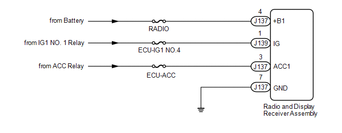
CAUTION / NOTICE / HINT

NOTICE:

Inspect the fuses for circuits related to this system before performing the following procedure.

PROCEDURE

1.

CHECK HARNESS AND CONNECTOR (RADIO AND DISPLAY RECEIVER ASSEMBLY - BATTERY AND GROUND)

(a) Disconnect the radio and display receiver assembly connector.

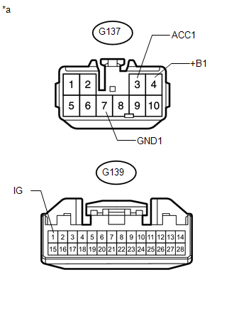
(b) Measure the resistance according to the value(s) in the table below.

Standard Resistance:

Tester Connection

Condition

Specified Condition

J137-7 (GND1) - Body ground

Always

Below 1 Ω

(c) Measure the voltage according to the value(s) in the table below.

Standard Voltage:

Tester Connection

Condition

Specified Condition

J137-4 (+B1) - Body ground

Always

11 to 14 V

J137-3 (ACC1) - Body ground

Ignition switch ACC

11 to 14 V

J139-1 (IG) - Body ground

Ignition switch ON

11 to 14 V

Text in Illustration

*a

Front view of wire harness connector

(to Radio and Display Receiver Assembly)

OK

PROCEED TO NEXT SUSPECTED AREA SHOWN IN PROBLEM SYMPTOMS TABLE

NG

REPAIR OR REPLACE HARNESS OR CONNECTOR

    Radio Broadcast cannot be Received (Bad Reception)

    Registered Device cannot be Deleted

    See More:

    Toyota Tundra Owners Manual > Using the driving support systems: Trailer brake controller
    Summary of functions The trailer brakes can be controlled by the Trailer brake controller via the 7-pin connector. By selecting the type of brakes that are being used on the trailer (electric or electric-over-hydraulic) and setting the gain for the controller, the manual TRAILER BRAKE OUTPUT slider ...

    Toyota Tundra Owners Manual

    Toyota Tundra Service Manual

    © 2024 Copyright www.ttundra.com
    0.0098