Toyota Tundra Service Manual: Voltage Meter Malfunction

DESCRIPTION

The voltmeter indicates the voltage applied to the IG+ terminal of the combination meter assembly.

WIRING DIAGRAM
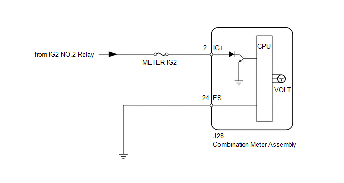
CAUTION / NOTICE / HINT

NOTICE:

Inspect the fuses for circuits related to this system before performing procedure.

PROCEDURE

1.

PERFORM ACTIVE TEST USING TECHSTREAM (VOLTMETER)

(a) Operate the Techstream according to the display and select "Active Test" (See page ).

Combination Meter:

Tester Display

Test Part

Control Range

Diagnostic Note

Volt Meter Operation

Voltmeter

OFF, 0 V, 3 V, 6V , 9 V, 12 V, 15 V or 18 V

Perform the test with the vehicle stopped and engine idling

OK:

Needle indication is normal.

NG

REPLACE COMBINATION METER ASSEMBLY

OK

2.

CHECK HARNESS AND CONNECTOR (COMBINATION METER ASSEMBLY - BATTERY AND BODY GROUND)

*a

Rear view of wire harness connector

(to Combination Meter Assembly)

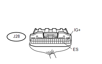
(a) Disconnect the J28 combination meter assembly connector.

(b) Measure the resistance and voltage according to the value(s) in the table below.

Standard Resistance:

Tester Connection

Condition

Specified Condition

J28-24 (ES) - Body ground

Always

Below 1 Ω

Standard Voltage:

Tester Connection

Switch Condition

Specified Condition

J28-2 (IG+) - Body ground

Ignition switch ON

11 to 14 V

Ignition switch off

Below 1 V

OK

REPLACE COMBINATION METER ASSEMBLY

NG

REPAIR OR REPLACE HARNESS OR CONNECTOR

    Lost Communication with Cruise Control Front Distance Range Sensor (U0235)

    Mirror

    See More:

    Toyota Tundra Service Manual > Cargo Light Switch: Inspection
    INSPECTION PROCEDURE 1. INSPECT DECK LIGHT SWITCH ASSEMBLY (a) Check the resistance. (1) Measure the resistance according to the value(s) in the table below. Standard Resistance: Tester Connection Switch Condition Specified Condition 5 (CCTY) - 9 (CGON) Cargo light switch ON Below 1 Ω Cargo light s ...

    Toyota Tundra Owners Manual

    Toyota Tundra Service Manual

    © 2024 Copyright www.ttundra.com
    0.0112