Toyota Tundra Service Manual: Inspection

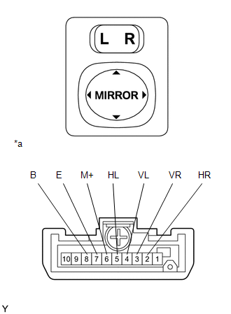
INSPECTION

PROCEDURE

1. INSPECT OUTER MIRROR SWITCH ASSEMBLY (w/o Retract Mirror)

(a) Check the resistance.

(1) Select "L" on the left/right adjustment switch.

(2) Measure the resistance according to the value(s) in the table below.

Standard Resistance:

Tester Connection

Condition

Specified Condition

4 (VL) - 8 (B)

6 (M+) - 7 (E)

UP

Pressed

Below 1 Ω

Not pressed

10 kΩ or higher

4 (VL) - 7 (E)

6 (M+) - 8 (B)

DOWN

Pressed

Below 1 Ω

Not pressed

10 kΩ or higher

5 (HL) - 8 (B)

6 (M+) - 7 (E)

LEFT

Pressed

Below 1 Ω

Not pressed

10 kΩ or higher

5 (HL) - 7 (E)

6 (M+) - 8 (B)

RIGHT

Pressed

Below 1 Ω

Not pressed

10 kΩ or higher

Text in Illustration

*a

Component without harness connected

(Outer Mirror Switch Assembly)

If the result is not as specified, replace the outer mirror switch assembly.

(3) Select "R" on the left/right adjustment switch.

(4) Measure the resistance according to the value(s) in the table below.

Standard Resistance:

Tester Connection

Condition

Specified Condition

3 (VR) - 8 (B)

6 (M+) - 7 (E)

UP

Pressed

Below 1 Ω

Not pressed

10 kΩ or higher

3 (VR) - 7 (E)

6 (M+) - 8 (B)

DOWN

Pressed

Below 1 Ω

Not pressed

10 kΩ or higher

2 (HR) - 8 (B)

6 (M+) - 7 (E)

LEFT

Pressed

Below 1 Ω

Not pressed

10 kΩ or higher

2 (HR) - 7 (E)

6 (M+) - 8 (B)

RIGHT

Pressed

Below 1 Ω

Not pressed

10 kΩ or higher

If the result is not as specified, replace the outer mirror switch assembly.

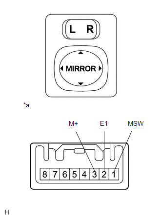
2. INSPECT OUTER MIRROR SWITCH ASSEMBLY (w/o Retract Mirror, w/ Memory)

(a) Inspect the outer mirror switch assembly.

(1) Select "L" on the left/right adjustment switch.

(2) Measure the resistance according to the value(s) in the table below.

Standard Resistance:

Tester Connection

Condition

Specified Condition

3 (M+) - 2 (E1)

UP

Pressed

100 Ω

Not pressed

10 kΩ or higher

3 (M+) - 2 (E1)

DOWN

Pressed

470 Ω

Not pressed

10 kΩ or higher

3 (M+) - 2 (E1)

LEFT

Pressed

800 Ω

Not pressed

10 kΩ or higher

3 (M+) - 2 (E1)

RIGHT

Pressed

250 Ω

Not pressed

10 kΩ or higher

1 (MSW) - 2 (E1)

L switch

Pressed

100 Ω

Not pressed

10 kΩ or higher

Text in Illustration

*a

Component without harness connected

(Outer Mirror Switch Assembly)

If the result is not as specified, replace the outer mirror switch assembly.

(3) Select "R" on the left/right adjustment switch.

(4) Using an ohmmeter, measure the resistance and check the results in accordance with the value(s) in the table below.

Standard Resistance:

Tester Connection

Condition

Specified Condition

3 (M+) - 2 (E1)

UP

Pressed

100 Ω

Not pressed

10 kΩ or higher

3 (M+) - 2 (E1)

DOWN

Pressed

470 Ω

Not pressed

10 kΩ or higher

3 (M+) - 2 (E1)

LEFT

Pressed

800 Ω

Not pressed

10 kΩ or higher

3 (M+) - 2 (E1)

RIGHT

Pressed

250 Ω

Not pressed

10 kΩ or higher

1 (MSW) - 2 (E1)

R switch

Pressed

Below 1 Ω

Not pressed

10 kΩ or higher

If the result is not as specified, replace the outer mirror switch assembly.

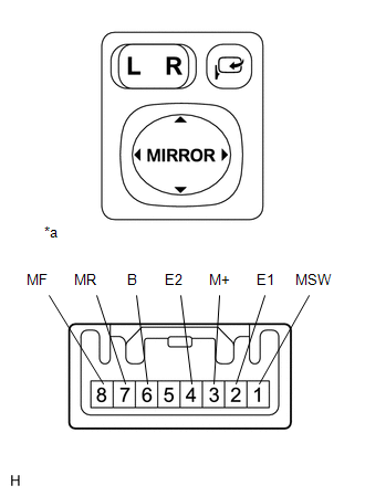
3. INSPECT OUTER MIRROR SWITCH ASSEMBLY (w/ Retract Mirror)

(a) Inspect the outer mirror switch assembly.

(1) Select "L" on the left/right adjustment switch.

(2) Measure the resistance according to the value(s) in the table below.

Standard Resistance:

Tester Connection

Condition

Specified Condition

3 (M+) - 2 (E1)

UP

Pressed

100 Ω

Not pressed

10 kΩ or higher

3 (M+) - 2 (E1)

DOWN

Pressed

470 Ω

Not pressed

10 kΩ or higher

3 (M+) - 2 (E1)

LEFT

Pressed

800 Ω

Not pressed

10 kΩ or higher

3 (M+) - 2 (E1)

RIGHT

Pressed

250 Ω

Not pressed

10 kΩ or higher

1 (MSW) - 2 (E1)

L switch

Pressed

100 Ω

Not pressed

10 kΩ or higher

Text in Illustration

*a

Component without harness connected

(Outer Mirror Switch Assembly)

If the result is not as specified, replace the outer mirror switch assembly.

(3) Select "R" on the left/right adjustment switch.

(4) Using an ohmmeter, measure the resistance and check the results in accordance with the value(s) in the table below.

Standard Resistance:

Tester Connection

Condition

Specified Condition

3 (M+) - 2 (E1)

UP

Pressed

100 Ω

Not pressed

10 kΩ or higher

3 (M+) - 2 (E1)

DOWN

Pressed

470 Ω

Not pressed

10 kΩ or higher

3 (M+) - 2 (E1)

LEFT

Pressed

800 Ω

Not pressed

10 kΩ or higher

3 (M+) - 2 (E1)

RIGHT

Pressed

250 Ω

Not pressed

10 kΩ or higher

1 (MSW) - 2 (E1)

R switch

Pressed

Below 1 Ω

Not pressed

10 kΩ or higher

If the result is not as specified, replace the outer mirror switch assembly.

(b) Inspect the retract switch.

(1) Measure the resistance according to the value(s) in the table below.

Standard Resistance:

Tester Connection

Condition

Specified Condition

6 (B) - 7 (MR)

8 (MF) - 4 (E2)

Pressed

(Retracts)

Below 1 Ω

Not pressed

10 kΩ or higher

6 (B) - 8 (MF)

4 (E2) - 7 (MR)

Pressed

(Driving position)

Below 1 Ω

Not pressed

10 kΩ or higher

If the result is not as specified, replace the outer mirror switch assembly.

    Components

    Installation

    See More:

    Toyota Tundra Service Manual > Clearance Warning Ecu: Removal
    REMOVAL PROCEDURE 1. PRECAUTION NOTICE: After turning the ignition switch off, waiting time may be required before disconnecting the cable from the battery terminal. Therefore, make sure to read the disconnecting the cable from the battery terminal notice before proceeding with work (See page ). 2. ...

    Toyota Tundra Owners Manual

    Toyota Tundra Service Manual

    © 2024 Copyright www.ttundra.com
    0.0181