Toyota Tundra Service Manual: Power Retractable Mirrors do not Operate with Power Retract Mirror Switch

Toyota Tundra Service Manual / Vehicle Interior / Mirror / Power Mirror Control System(w/ Memory) / Power Retractable Mirrors do not Operate with Power Retract Mirror Switch

DESCRIPTION

When the outer mirror switch assembly (mirror retract switch) is operated, return/retract signals are sent to the main body ECU (multiplex network body ECU). The main body ECU (multiplex network body ECU) sends return/retract signals to the outer mirror control ECU assembly via CAN communication. The outer mirror control ECU assembly returns and retracts the outer rear view mirror assembly based on the received signals.

WIRING DIAGRAM

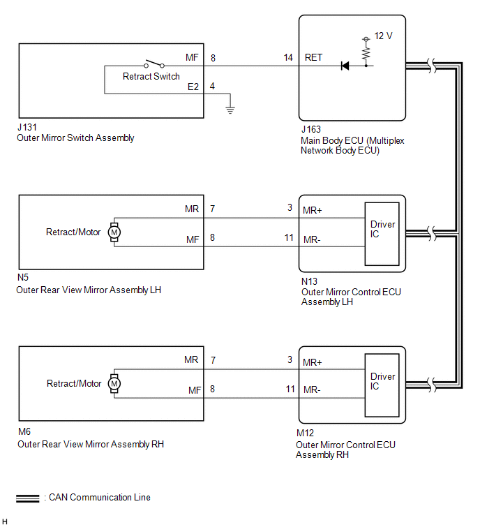
CAUTION / NOTICE / HINT

NOTICE:

First perform the communication function inspections in How to Proceed with Troubleshooting to confirm that there are no CAN communication malfunctions before troubleshooting this problem.

Click here

PROCEDURE

1.

READ VALUE USING TECHSTREAM (OUTER MIRROR FOLD SW)

(a) Using the Techstream, read the Data List.

Click here

Tester Display

Measurement Item/Range

Normal Condition

Diagnostic Note

Outer Mirror Fold SW

Mirror retract switch signal / ON or OFF

ON: Mirror retract switch is ON (retracting)

OFF: Mirror retract switch is OFF

-

OK:

On the Techstream screen, ON or OFF is displayed for each item according to the table above.

NG

GO TO STEP 7

OK

2.

CHECK MALFUNCTIONING PARTS

(a) Check the malfunctioning parts.

Click here

Result

Proceed to

Both mirrors are malfunctioning

A

LH side mirror is malfunctioning

B

RH side mirror is malfunctioning

C

A

REPLACE MAIN BODY ECU (MULTIPLEX NETWORK BODY ECU)

C

GO TO STEP 5

B

3.

INSPECT OUTER REAR VIEW MIRROR ASSEMBLY LH (POWER RETRACT FUNCTION)

(a) Remove the outer rear view mirror assembly LH.

Click here

(b) Inspect the outer rear view mirror assembly LH.

Click here

NG

REPLACE OUTER REAR VIEW MIRROR ASSEMBLY LH

OK

4.

CHECK HARNESS AND CONNECTOR (OUTER REAR VIEW MIRROR ASSEMBLY LH - OUTER MIRROR CONTROL ECU ASSEMBLY LH)

(a) Disconnect the N5 outer rear view mirror assembly LH connector.

(b) Disconnect the N13 outer mirror control ECU assembly LH connector.

(c) Measure the resistance according to the value(s) in the table below.

Standard Resistance:

Tester Connection

Condition

Specified Condition

N5-7 (MR) - N13-3 (MR+)

Always

Below 1 Ω

N5-8 (MF) - N13-11 (MR-)

Always

Below 1 Ω

N5-7 (MR) or N13-3 (MR+) - Body ground

Always

10 kΩ or higher

N5-8 (MF) or N13-11 (MR-) - Body ground

Always

10 kΩ or higher

OK

REPLACE OUTER MIRROR CONTROL ECU ASSEMBLY LH

NG

REPAIR OR REPLACE HARNESS OR CONNECTOR

5.

INSPECT OUTER REAR VIEW MIRROR ASSEMBLY RH (POWER RETRACT FUNCTION)

(a) Remove the outer rear view mirror assembly RH.

Click here

(b) Inspect the outer rear view mirror assembly RH.

Click here

NG

REPLACE OUTER REAR VIEW MIRROR ASSEMBLY RH

OK

6.

CHECK HARNESS AND CONNECTOR (OUTER REAR VIEW MIRROR ASSEMBLY RH - OUTER MIRROR CONTROL ECU ASSEMBLY RH)

(a) Disconnect the M6 outer rear view mirror assembly RH connector.

(b) Disconnect the M12 outer mirror control ECU assembly RH connector.

(c) Measure the resistance according to the value(s) in the table below.

Standard Resistance:

Tester Connection

Condition

Specified Condition

M6-7 (MR) - M12-3 (MR+)

Always

Below 1 Ω

M6-8 (MF) - M12-11 (MR-)

Always

Below 1 Ω

M6-7 (MR) or M12-3 (MR+) - Body ground

Always

10 kΩ or higher

M6-8 (MF) or M12-11 (MR-) - Body ground

Always

10 kΩ or higher

OK

REPLACE OUTER MIRROR CONTROL ECU ASSEMBLY RH

NG

REPAIR OR REPLACE HARNESS OR CONNECTOR

7.

INSPECT OUTER MIRROR SWITCH ASSEMBLY (MIRROR RETRACT SWITCH)

(a) Remove the outer mirror switch assembly.

Click here

(b) Inspect the outer mirror switch assembly.

Click here

NG

REPLACE OUTER MIRROR SWITCH ASSEMBLY

OK

8.

CHECK HARNESS AND CONNECTOR (OUTER MIRROR SWITCH ASSEMBLY - MAIN BODY ECU [MULTIPLEX NETWORK BODY ECU])

(a) Disconnect the J131 outer mirror switch assembly connector.

(b) Disconnect the J163 main body ECU (multiplex network body ECU) connector.

(c) Measure the resistance according to the value(s) in the table below.

Standard Resistance:

Tester Connection

Condition

Specified Condition

J131-8 (MF) - J163-14 (RET)

Always

Below 1 Ω

J131-8 (MF) or J163-14 (RET) - Body ground

Always

10 kΩ or higher

J131-4 (E2) - Body ground

Always

10 kΩ or higher

OK

REPLACE MAIN BODY ECU (MULTIPLEX NETWORK BODY ECU)

NG

REPAIR OR REPLACE HARNESS OR CONNECTOR

    Power Mirrors do not Return to Memorized Position

    Problem Symptoms Table

    See More:

    Toyota Tundra Service Manual > Lumbar Support Adjuster Assembly: Removal
    REMOVAL CAUTION / NOTICE / HINT CAUTION: Wear protective gloves. Sharp areas on the parts may injure your hands. HINT: Use the same procedure for the RH and LH sides. The procedure listed below is for the LH side. PROCEDURE 1. REMOVE FRONT SEAT ASSEMBLY LH (See page ) 2. REMOVE FRONT SEAT CUSHION SH ...

    Toyota Tundra Owners Manual

    Toyota Tundra Service Manual

    © 2024 Copyright www.ttundra.com
    0.0237