REMOVAL PROCEDURE 1. REMOVE FRONT SEAT ASSEMBLY LH (for Manual Seat) (See page 2. REMOVE FRONT SEAT ASSEMBLY RH (for Manual Seat) HINT: Use the same procedure described for the LH side. 3. REMOVE FRONT SEAT ASSEMBLY LH (for Power Seat) (See page 4. REMOVE FRONT SEAT ASSEMBLY RH (for Power Seat) HINT: Use the same procedure described for the LH side. 5. REMOVE CENTER FRONT SEAT ASSEMBLY (See page 6. REMOVE POWER OUTLET SOCKET ASSEMBLY
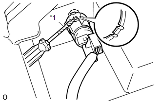
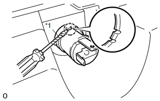
(b) Using a screwdriver, detach the claw and remove the power outlet socket assembly. HINT: Tape the screwdriver tip before use. Text in Illustration
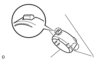
7. REMOVE POWER OUTLET SOCKET COVER
8. REMOVE CENTER SEATBACK PANEL (for Double Cab)
9. REMOVE REAR POWER OUTLET SOCKET ASSEMBLY (for Double Cab)
10. REMOVE REAR POWER OUTLET SOCKET COVER (for Double Cab) 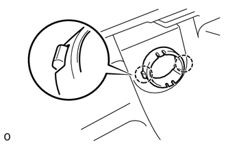
(a) Detach the 2 claws and remove the rear power outlet socket cover. |
Toyota Tundra Service Manual > Pre-collision System: Vehicle Information Not Obtained (C1A02)
DESCRIPTION When a new millimeter wave radar sensor assembly is installed, it receives vehicle specification information from the main body ECU (multiplex network body ECU) and stores the information. DTC C1A02 is stored when the millimeter wave radar sensor assembly receives the vehicle specificati ...

 )
)