REMOVAL PROCEDURE 1. REMOVE LOWER CENTER INSTRUMENT COVER (for Column Shift Type)
2. REMOVE SHIFT LEVER KNOB SUB-ASSEMBLY (for Floor Shift Type)
3. REMOVE UPPER REAR CONSOLE PANEL SUB-ASSEMBLY (for Floor Shift Type)
4. REMOVE UPPER CONSOLE PANEL SUB-ASSEMBLY (for Floor Shift Type)
5. REMOVE REAR CONSOLE END PANEL SUB-ASSEMBLY (for Floor Shift Type)
6. REMOVE CONSOLE BOX CARPET (for Floor Shift Type)
7. REMOVE REAR CONSOLE BOX ASSEMBLY (for Floor Shift Type)
8. REMOVE FRONT CONSOLE BOX (for Floor Shift Type)
9. REMOVE AIR CONDITIONING CONTROL ASSEMBLY WITH LOWER CENTER INSTRUMENT PANEL FINISH PANEL
10. REMOVE LOWER CENTER INSTRUMENT PANEL FINISH PANEL
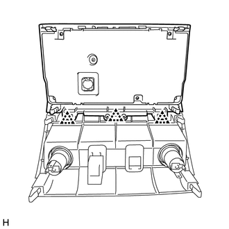
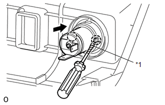
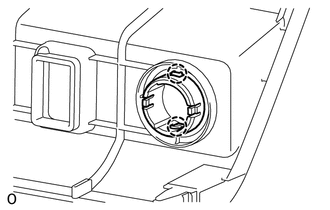
11. REMOVE POWER OUTLET SOCKET ASSEMBLY
12. REMOVE POWER OUTLET SOCKET COVER
|
Toyota Tundra Service Manual > Front Seat Cushion Heater(for Power Seat): Inspection
INSPECTION PROCEDURE 1. INSPECT FRONT SEAT CUSHION HEATER ASSEMBLY LH (a) Check the resistance of the front seat cushion heater assembly LH. (1) Measure the resistance according to the value(s) in the table below. Standard Resistance: Tester Connection Condition Specified Condition 3 - 5 Seat cushio ...