
DESCRIPTION The No. 1 stereo jack adapter assembly sends an external device sound signal to the radio and display receiver assembly through this circuit. The sound signal that has been sent is amplified by the radio and display receiver assembly and then is sent to the speakers. If there is an open or short in the circuit, sound cannot be heard from the speakers even if there is no malfunction in the radio and display receiver assembly or speakers. WIRING DIAGRAM 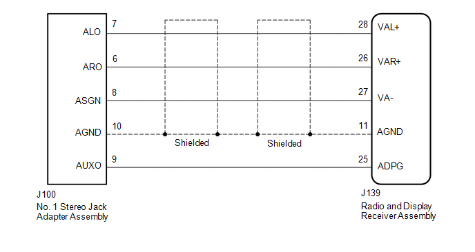 PROCEDURE
(a) Disconnect the J139 radio and display receiver assembly connector. (b) Disconnect the J100 No. 1 stereo jack adapter assembly connector. (c) Measure the resistance according to the value(s) in the table below. Standard Resistance:
|
Toyota Tundra Service Manual > Cargo Light Switch: Removal
REMOVAL PROCEDURE 1. REMOVE FRONT DOOR SCUFF PLATE LH for Double Cab: (See page ) for CrewMax: (See page ) 2. REMOVE COWL SIDE TRIM BOARD LH 3. REMOVE INSTRUMENT SIDE PANEL LH 4. REMOVE LOWER INSTRUMENT PANEL FINISH PANEL SUB-ASSEMBLY LH 5. REMOVE DECK LIGHT SWITCH ASSEMBLY (a) Using a screwdriver, ...


