DESCRIPTION This circuit sends an operation signal from the steering pad switch assembly to the radio and display receiver assembly. If there is an open in the circuit, the audio system cannot be operated using the steering pad switch assembly. If there is a short in the circuit, the same condition as when the switch is continuously depressed occurs. Therefore, the radio and display receiver assembly cannot be operated using the steering pad switch assembly, and the radio and display receiver assembly itself cannot function. WIRING DIAGRAM 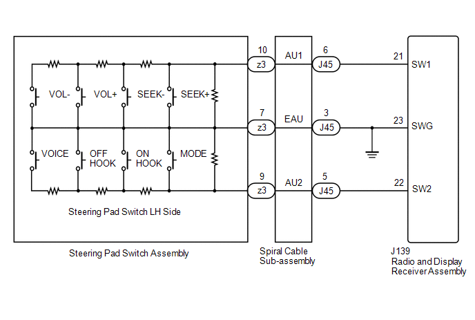 CAUTION / NOTICE / HINT CAUTION:
PROCEDURE
(a) Remove the steering pad switch assembly (See page
(b) Inspect the steering pad switch assembly (See page
(a) Remove the spiral cable sub-assembly (See page
(b) Inspect the spiral cable sub-assembly (See page
(a) Disconnect the J139 radio and display receiver assembly connector. (b) Disconnect the J45 spiral cable sub-assembly connector. (c) Measure the resistance according to the value(s) in the table below. Standard Resistance:
|
Toyota Tundra Service Manual > Fan: Installation
INSTALLATION PROCEDURE 1. INSTALL FAN (a) Install the fan to the fluid coupling with the 4 nuts. Torque: 10 N·m {102 kgf·cm, 7 ft·lbf} 2. INSTALL FAN SHROUD (a) Install the fan pulley to the fan bracket. (b) Place the fan shroud together with the fluid coupling fan between the radiator and engine ...

 ).
).


