DESCRIPTION
This DTC is output when the sliding roof drive gear (sliding roof ECU) detects
that the SLIDE or TILT switch in the roof console box (sliding roof switch) is stuck
for 30 seconds or more.
|
DTC Code
|
DTC Detection Condition
|
Trouble Area
|
|
B2342
|
Sliding roof drive gear (sliding roof ECU) detects that SLIDE or TILT
switch in roof console box is stuck for 30 seconds or more
|
- Sliding roof switch
- Roof console box
- Harness and connector
- Sliding roof drive gear (sliding roof ECU)
|
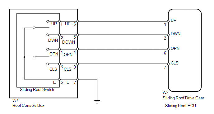
WIRING DIAGRAM
PROCEDURE
(a) Clear the DTCs (see page  ). ).
(b) Check for DTCs (see page ).
Result
|
Result
|
Proceed to
|
|
DTC B2342 is output
|
A
|
|
No DTC is output
|
B
|
| B |
 |
USE SIMULATION METHOD TO CHECK
|
| A |

|
|
|
2.
|
READ VALUE USING TECHSTREAM (SWITCH STATUS)
|
(a) Use the Data List to check if the sliding roof switch is functioning properly
(see page ).
Sliding Roof
|
Tester Display
|
Measurement Item/Range
|
Normal Condition
|
Diagnostic Note
|
|
Down Switch Failure (Current)
|
Down switch failure signal (Current)/ON or OFF
|
ON: Sliding roof tilt down signal failure (Current)
OFF: Sliding roof tilt down signal not fail (Current)
|
-
|
|
Up Switch Failure (Current)
|
Up switch failure signal (Current)/ON or OFF
|
ON: Sliding roof tilt up signal failure (Current)
OFF: Sliding roof tilt up signal not fail (Current)
|
-
|
|
Close Switch Failure (Current)
|
Close switch failure signal (Current)/ON or OFF
|
ON: Sliding roof tilt close signal failure (Current)
OFF: Sliding roof tilt close signal not fail (Current)
|
-
|
|
Open Switch Failure (Current)
|
Open switch failure signal (Current)/ON or OFF
|
ON: Sliding roof tilt open signal failure (Current)
OFF: Sliding roof tilt open signal not fail (Current)
|
-
|
|
Down Switch Failure (Past)
|
Down switch failure signal (Past)/ON or OFF
|
ON: Sliding roof tilt down signal failure (Past)
OFF: Sliding roof tilt down signal not fail (Past)
|
-
|
|
Up Switch Failure (Past)
|
Up switch failure signal (Past)/ON or OFF
|
ON: Sliding roof tilt up signal failure (Past)
OFF: Sliding roof tilt up signal not fail (Past)
|
-
|
|
Close Switch Failure (Past)
|
Close switch failure signal (Past)/ON or OFF
|
ON: Sliding roof tilt close signal failure (Current)
OFF: Sliding roof tilt close signal not fail (Current)
|
-
|
|
Open Switch Failure (Past)
|
Open switch failure signal (Past)/ON or OFF
|
ON: Sliding roof tilt open signal failure (Current)
OFF: Sliding roof tilt open signal not fail (Current)
|
-
|
OK:
The Techstream displays as shown in the table according to the operation of each
switch.
| OK |
|
REPLACE SLIDING ROOF DRIVE GEAR SUB-ASSEMBLY (SLIDING ROOF ECU)
|
| NG |
|
|
|
|
3.
|
INSPECT SLIDING ROOF SWITCH
|
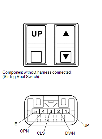
(a) Remove the sliding roof switch (see page
).
(b) Measure the resistance according to the value(s) in the table below.
Standard resistance:
|
Tester Connection
|
Switch Condition
|
Specified Condition
|
|
1 (UP) - 5 (E)
|
TILT switch is pressed to up
|
Below 1 Ω
|
|
1 (UP) - 5 (E)
|
TILT switch is not pressed to up
|
10 kΩ or higher
|
|
2 (DWN) - 5 (E)
|
TILT switch is pressed to down
|
Below 1 Ω
|
|
2 (DWN) - 5 (E)
|
TILT switch is not pressed to down
|
10 kΩ or higher
|
|
4 (OPN) - 5 (E)
|
SLIDE switch is pressed to open
|
Below 1 Ω
|
|
4 (OPN) - 5 (E)
|
SLIDE switch is not pressed to open
|
10 kΩ or higher
|
|
3 (CLS) - 5 (E)
|
SLIDE switch is pressed to close
|
Below 1 Ω
|
|
3 (CLS) - 5 (E)
|
SLIDE switch is not pressed to close
|
10 kΩ or higher
|
| NG |
|
REPLACE SLIDING ROOF SWITCH
|
| OK |
|
|
|
|
4.
|
INSPECT ROOF CONSOLE BOX ASSEMBLY
|
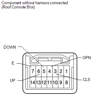
(a) Remove the roof console box with sliding roof switch (see page
).
(b) Measure the resistance according to the value(s) in the table below.
Standard resistance:
|
Tester Connection
|
Switch Condition
|
Specified Condition
|
|
6 (UP) - 7 (E)
|
TILT switch is pressed to up
|
Below 1 Ω
|
|
6 (UP) - 7 (E)
|
TILT switch is not pressed to up
|
10 kΩ or higher
|
|
5 (DOWN) - 7 (E)
|
TILT switch is pressed to down
|
Below 1 Ω
|
|
5 (DOWN) - 7 (E)
|
TILT switch is not pressed to down
|
10 kΩ or higher
|
|
4 (OPN) - 7 (E)
|
SLIDE switch is pressed to open
|
Below 1 Ω
|
|
4 (OPN) - 7 (E)
|
SLIDE switch is not pressed to open
|
10 kΩ or higher
|
|
3 (CLS) - 7 (E)
|
SLIDE switch is pressed to close
|
Below 1 Ω
|
|
3 (CLS) - 7 (E)
|
SLIDE switch is not pressed to close
|
10 kΩ or higher
|
| NG |
|
REPLACE ROOF CONSOLE BOX ASSEMBLY
|
| OK |
|
|
|
|
5.
|
CHECK HARNESS AND CONNECTOR (SLIDING ROOF ECU - ROOF CONSOLE BOX)
|
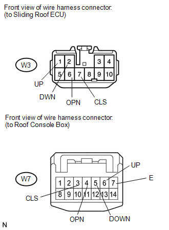
(a) Disconnect the W3 ECU connector.
(b) Disconnect the W7 roof console box connector.
(c) Measure the resistance according to the value(s) in the table below.
Standard resistance:
|
Tester Connection
|
Condition
|
Specified Condition
|
|
W3-1 (UP) - W7-6 (UP)
|
Always
|
Below 1 Ω
|
|
W3-2 (DWN) - W7-5 (DOWN)
|
Always
|
Below 1 Ω
|
|
W3-6 (OPN) - W7-4 (OPN)
|
Always
|
Below 1 Ω
|
|
W3-7 (CLS) - W7-3 (CLS)
|
Always
|
Below 1 Ω
|
|
W7-6 (UP) - Body ground
|
Always
|
10 kΩ or higher
|
|
W7-5 (DOWN) - Body ground
|
Always
|
10 kΩ or higher
|
|
W7-3 (CLS) - Body ground
|
Always
|
10 kΩ or higher
|
|
W7-4 (OPN) - Body ground
|
Always
|
10 kΩ or higher
|
|
W7-7 (E) - Body ground
|
Always
|
Below 1 Ω
|
| OK |
|
REPLACE SLIDING ROOF DRIVE GEAR SUB-ASSEMBLY
|
| NG |
|
REPAIR OR REPLACE HARNESS OR CONNECTOR
|
| 

