DESCRIPTION
If either the sliding function or tilt function does not operate, there may be
a malfunction in the sliding roof switch circuit.
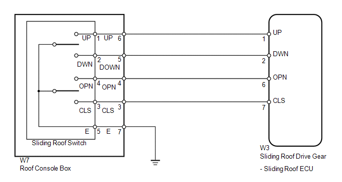
WIRING DIAGRAM

PROCEDURE
|
1.
|
PERFORM ACTIVE TEST USING TECHSTREAM (SLIDING ROOF OPERATION)
|
(a) Select the Active Test, use the Techstream to generate a control command,
and then check that the sliding roof operates (see page
 ). ).
Sliding Roof
|
Tester Display
|
Test Part
|
Control Range
|
Diagnostic Note
|
|
Slide Roof
|
Operate sliding roof SLIDE CLOSE/TILT UP or SLIDE OPEN/TILT DOWN
|
Clos/Up: Sliding roof SLIDE CLOSE or TILT UP operation occurs
Opn/Dwn: Sliding roof SLIDE OPEN or TILT DOWN operation occurs
OFF: Sliding roof is not operating
|
-
|
OK:
Sliding roof operates normally.
| NG |
 |
REPLACE SLIDING ROOF DRIVE GEAR SUB-ASSEMBLY (SLIDING ROOF ECU)
|
| OK |

|
|
|
2.
|
READ VALUE USING TECHSTREAM (SLIDING ROOF SWITCH)
|
(a) Use the Data List to check if the sliding roof switch is functioning properly
(see page  ). ).
Sliding Roof
|
Tester Display
|
Test Part
|
Control Range
|
Diagnostic Note
|
|
Open Switch
|
Sliding roof open switch signal/ON or OFF
|
ON: SLIDE switch is pressed to open
OFF: SLIDE switch is not pressed to open
|
-
|
|
Close Switch
|
Sliding roof close switch signal/ON or OFF
|
ON: SLIDE switch is pressed to close
OFF: SLIDE switch is not pressed to close
|
-
|
|
Up Switch
|
Sliding roof up switch signal/ON or OFF
|
ON: TILT switch is pressed to up
OFF: TILT switch is not pressed to up
|
-
|
|
Down Switch
|
Sliding roof down switch signal/ON or OFF
|
ON: TILT switch is pressed to down
OFF: TILT switch is not pressed to down
|
-
|
OK:
The Techstream displays as shown in the table according to the operation of each
switch.
| OK |
 |
REPLACE SLIDING ROOF DRIVE GEAR SUB-ASSEMBLY (SLIDING ROOF ECU)
|
| NG |

|
|
|
3.
|
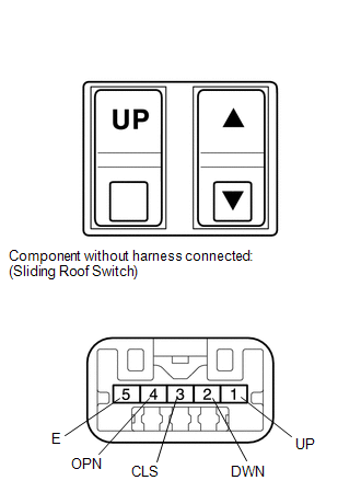
INSPECT SLIDING ROOF SWITCH
|

(a) Remove the sliding roof switch (see page  ).
).
(b) Measure the resistance according to the value(s) in the table below.
Standard resistance:
|
Tester Connection
|
Switch Condition
|
Specified Condition
|
|
1 (UP) - 5 (E)
|
TILT switch is pressed to up
|
Below 1 Ω
|
|
1 (UP) - 5 (E)
|
TILT switch is not pressed to up
|
10 kΩ or higher
|
|
2 (DWN) - 5 (E)
|
TILT switch is pressed to down
|
Below 1 Ω
|
|
2 (DWN) - 5 (E)
|
TILT switch is not pressed to down
|
10 kΩ or higher
|
|
4 (OPN) - 5 (E)
|
SLIDE switch is pressed to open
|
Below 1 Ω
|
|
4 (OPN) - 5 (E)
|
SLIDE switch is not pressed to open
|
10 kΩ or higher
|
|
3 (CLS) - 5 (E)
|
SLIDE switch is pressed to close
|
Below 1 Ω
|
|
3 (CLS) - 5 (E)
|
SLIDE switch is not pressed to close
|
10 kΩ or higher
|
| NG |
 |
REPLACE SLIDING ROOF SWITCH
|
| OK |

|
|
|
4.
|
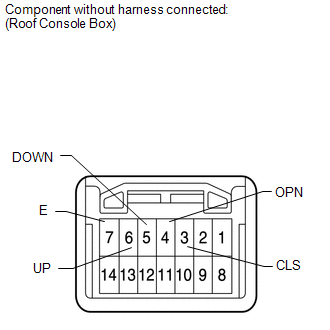
INSPECT ROOF CONSOLE BOX ASSEMBLY
|

(a) Remove the roof console box with sliding roof switch (see page
 ). ).
(b) Measure the resistance according to the value(s) in the table below.
Standard resistance:
|
Tester Connection
|
Switch Condition
|
Specified Condition
|
|
6 (UP) - 7 (E)
|
TILT switch is pressed to up
|
Below 1 Ω
|
|
6 (UP) - 7 (E)
|
TILT switch is not pressed to up
|
10 kΩ or higher
|
|
5 (DOWN) - 7 (E)
|
TILT switch is pressed to down
|
Below 1 Ω
|
|
5 (DOWN) - 7 (E)
|
TILT switch is not pressed to down
|
10 kΩ or higher
|
|
4 (OPN) - 7 (E)
|
SLIDE switch is pressed to open
|
Below 1 Ω
|
|
4 (OPN) - 7 (E)
|
SLIDE switch is not pressed to open
|
10 kΩ or higher
|
|
3 (CLS) - 7 (E)
|
SLIDE switch is pressed to close
|
Below 1 Ω
|
|
3 (CLS) - 7 (E)
|
SLIDE switch is not pressed to close
|
10 kΩ or higher
|
| NG |
 |
REPLACE ROOF CONSOLE BOX ASSEMBLY
|
| OK |

|
|
|
5.
|
CHECK HARNESS AND CONNECTOR (SLIDING ROOF ECU - ROOF CONSOLE BOX)
|
|
(a) Disconnect the W3 ECU connector.
|
|
(b) Disconnect the W7 switch connector.
(c) Measure the resistance according to the value(s) in the table below.
Standard resistance:
|
Tester Connection
|
Condition
|
Specified Condition
|
|
W3-1 (UP) - W7-6 (UP)
|
Always
|
Below 1 Ω
|
|
W3-2 (DWN) - W7-5 (DOWN)
|
Always
|
Below 1 Ω
|
|
W3-6 (OPN) - W7-4 (OPN)
|
Always
|
Below 1 Ω
|
|
W3-7 (CLS) - W7-3 (CLS)
|
Always
|
Below 1 Ω
|
|
W7-6 (UP) - Body ground
|
Always
|
10 kΩ or higher
|
|
W7-5 (DOWN) - Body ground
|
Always
|
10 kΩ or higher
|
|
W7-3 (CLS) - Body ground
|
Always
|
10 kΩ or higher
|
|
W7-4 (OPN) - Body ground
|
Always
|
10 kΩ or higher
|
|
W7-7 (E) - Body ground
|
Always
|
Below 1 Ω
|
| OK |
 |
REPLACE SLIDING ROOF DRIVE GEAR SUB-ASSEMBLY (SLIDING ROOF ECU)
|
| NG |
 |
REPAIR OR REPLACE HARNESS OR CONNECTOR
|
| 

