SYSTEM DIAGRAM 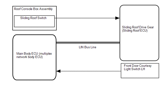 Communication table Communication table
|
Toyota Tundra Service Manual > Parking Brake: Parking Brake System
AdjustmentADJUSTMENT PROCEDURE 1. REMOVE REAR WHEEL 2. ADJUST PARKING BRAKE SHOE CLEARANCE (a) Temporarily install the hub nuts. (b) Remove the hole plug. (c) Insert a screwdriver into the adjustment hole of the disc. Rotate the adjustment wheel in the "X" direction until the shoes are locked. Then ...


