REMOVAL PROCEDURE 1. REMOVE FRONT PILLAR GARNISH LH 2. REMOVE FRONT PILLAR GARNISH RH 3. REMOVE NO. 1 INSTRUMENT PANEL SPEAKER PANEL SUB-ASSEMBLY 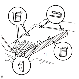 Text in Illustration Text in Illustration
(a) Apply protective tape as shown in the illustration. (b) Using moulding remover B, detach the 3 clips, 3 claws and 2 guides and remove the No. 1 instrument panel speaker panel sub-assembly. 4. REMOVE NO. 2 INSTRUMENT PANEL SPEAKER PANEL SUB-ASSEMBLY 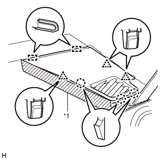 Text in Illustration Text in Illustration
(a) Apply protective tape as shown in the illustration. (b) Using moulding remover B, detach the 3 clips, 3 claws and 2 guides and remove the No. 2 instrument panel speaker panel sub-assembly. 5. REMOVE FRONT NO. 2 SPEAKER ASSEMBLY LH 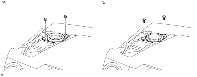 Text in Illustration Text in Illustration
(a) Remove the 2 bolts. (b) Disconnect the connector and remove the front No. 2 speaker assembly LH. NOTICE: Do not touch the cone part of the speaker. 6. REMOVE FRONT NO. 2 SPEAKER ASSEMBLY RH 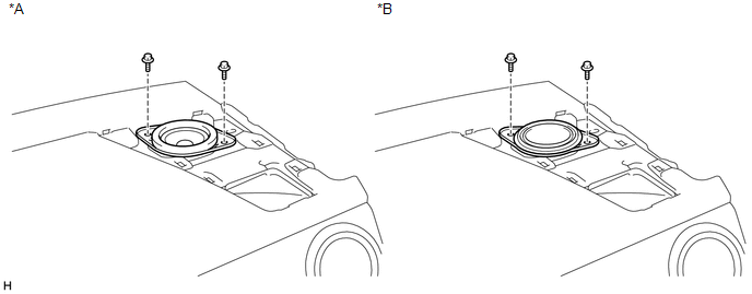 Text in Illustration Text in Illustration
(a) Remove the 2 bolts. (b) Disconnect the connector and remove the front No. 2 speaker assembly RH. NOTICE: Do not touch the cone part of the speaker. 7. REMOVE NO. 1 SPEAKER HOLE COVER 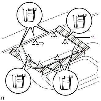 Text in Illustration Text in Illustration
(a) Apply protective tape as shown in the illustration. (b) Using moulding remover B, detach the 8 clips and remove the No. 1 speaker hole cover. 8. REMOVE FRONT NO. 4 SPEAKER ASSEMBLY (for 12 Speakers) 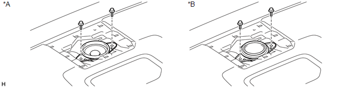 Text in Illustration Text in Illustration
(a) Remove the 2 bolts. (b) Disconnect the connector and remove the front No. 4 speaker assembly. NOTICE: Do not touch the cone part of the speaker. |
Toyota Tundra Service Manual > Lighting System: Automatic High Beam System (B124B)
DESCRIPTION The main body ECU (multiplex network body ECU) determines the status of the automatic high beam system based on the automatic high beam system signal from the forward recognition camera. DTC No. Detection Item DTC Detection Condition Trouble Area B124B Automatic High Beam System Malfunct ...


