DESCRIPTION
The power window regulator sub-assembly consists of the motor, regulator and
ECU. The power window regulator motor is driven by operating the power window switch.
This DTC is output when the ECU built into the regulator motor determines that the
power window switch is stuck.
NOTICE:
Master Switch
|
DTC Code
|
DTC Detection Condition
|
Trouble Area
|
|
B2312
|
- The power window regulator master switch is stuck.
- The power window regulator master switch is held in the same position
for more than 20 seconds.
|
- Power window regulator master switch assembly
- Harness or connector
- Power window regulator master switch assembly held in same position
for more than 20 seconds
|
Driver Side Motor
|
DTC Code
|
DTC Detection Condition
|
Trouble Area
|
|
B2312
|
- The power window regulator master switch stuck.
- The power window regulator master switch is held in the same position
for more than 20 seconds.
|
- Power window regulator master switch assembly
- Front power window regulator motor assembly LH
- Harness or connector
- Power window regulator master switch assembly held in same position
for more than 20 seconds
|
Front Passenger Side Motor
|
DTC Code
|
DTC Detection Condition
|
Trouble Area
|
|
B2312
|
- The power window regulator switch is stuck.
- The power window regulator switch is held in the same position for
more than 20 seconds.
|
- Power window regulator switch assembly
- Front power window regulator motor assembly RH
- Harness or connector
- Power window regulator switch assembly held in same position for
more than 20 seconds
|
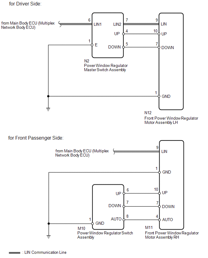
WIRING DIAGRAM
PROCEDURE
|
1.
|
CHECK LIN COMMUNICATION SYSTEM
|
(a) Check for LIN communication system DTCs related to the power window control
system (See page  ). ).
OK:
LIN communication system DTCs are not output.
| NG |
 |
GO TO LIN COMMUNICATION SYSTEM
|
| OK |

|
|
(a) Check where DTC B2312 is output from.
Result
|
Result
|
Proceed to
|
|
DTC B2312 output from power window regulator master switch assembly.
|
A
|
|
DTC B2312 output from front power window regulator motor assembly LH.
|
B
|
|
DTC B2312 output from front power window regulator motor assembly RH.
|
C
|
| B |
|
GO TO STEP 4
|
| C |
|
GO TO STEP 6
|
| A |
|
|
|
|
3.
|
READ VALUE USING TECHSTREAM (MASTER SWITCH)
|
(a) Use the Data List to check if the master switch is functioning properly.
Master Switch
|
Tester Display
|
Measurement Item/Range
|
Normal Condition
|
Diagnostic Note
|
|
D Door P/W Auto SW
|
Driver side power window auto UP/DOWN switch signal / ON or OFF
|
ON: Driver side switch of master switch operated
OFF: Driver side switch of master switch not operated
|
-
|
|
P Door P/W Auto SW
|
Front passenger side power window remote auto UP/DOWN switch signal /
ON or OFF
|
ON: Front passenger side switch of master switch operated
OFF: Front passenger side switch of master switch not operated
|
-
|
|
P Door P/W Up SW
|
Front passenger side power window remote manual UP switch signal / ON
or OFF
|
ON: Front passenger side switch of master switch operated
OFF: Front passenger side switch of master switch not operated
|
-
|
|
P Door P/W Down SW
|
Front passenger side power window remote manual DOWN switch signal /
ON or OFF
|
ON: Front passenger side switch of master switch operated
OFF: Front passenger side switch of master switch not operated
|
-
|
|
Window Lock Switch Status
|
Power window LOCK switch / ON or OFF
|
ON: Power window lock switch in LOCK position
OFF: Power window lock switch in UNLOCK position
|
-
|
OK:
The Techstream display changes normally when master switch is operated.
| OK |
|
END (DUE TO KEEPING SWITCH OPERATED FOR 20 SECONDS OR MORE)
|
| NG |
|
REPLACE POWER WINDOW REGULATOR MASTER SWITCH ASSEMBLY
|
|
4.
|
READ VALUE USING TECHSTREAM (DRIVER SIDE MOTOR)
|
(a) Use the Data List to check if the driver side motor is functioning properly.
D-Door Motor
|
Tester Display
|
Measurement Item/Range
|
Normal Condition
|
Diagnostic Note
|
|
D Door P/W Auto SW
|
Driver side power window auto UP/DOWN switch signal / ON or OFF
|
ON: Driver side switch operated
OFF: Driver side switch not operated
|
-
|
|
D Door P/W Up SW
|
Driver side power window MANUAL UP switch signal / ON or OFF
|
ON: Driver side switch operated
OFF: Driver side switch not operated
|
-
|
|
D Door P/W Down SW
|
Driver side power window MANUAL DOWN switch signal / ON or OFF
|
ON: Driver side switch operated
OFF: Driver side switch not operated
|
-
|
OK:
The Techstream display changes normally when master switch is operated.
| OK |
|
END (DUE TO KEEPING SWITCH OPERATED FOR 20 SECONDS OR MORE)
|
| NG |
|
|
|
|
5.
|
CHECK HARNESS AND CONNECTOR (MASTER SWITCH - DRIVER SIDE MOTOR)
|
(a) Disconnect the N2 master switch connector.
(b) Disconnect the N12 motor connector.
(c) Measure the resistance according to the value(s) in the table below.
Standard Resistance:
|
Tester Connection
|
Condition
|
Specified Condition
|
|
N2-4 (UP) - N12-10 (UP)
|
Always
|
Below 1 Ω
|
|
N2-5 (DOWN) - N12-7 (DOWN)
|
Always
|
Below 1 Ω
|
|
N2-4 (UP) - Body ground
|
Always
|
10 kΩ or higher
|
|
N2-5 (DOWN) - Body ground
|
Always
|
10 kΩ or higher
|
| OK |
|
REPLACE POWER WINDOW REGULATOR MOTOR ASSEMBLY LH
|
| NG |
|
REPAIR OR REPLACE HARNESS OR CONNECTOR
|
|
6.
|
READ VALUE USING TECHSTREAM (FRONT PASSENGER SIDE MOTOR)
|
(a) Use the Data List to check if the front passenger side motor is functioning
properly.
P-Door Motor
|
Tester Display
|
Measurement Item/Range
|
Normal Condition
|
Diagnostic Note
|
|
P Door P/W Auto SW
|
Front passenger side power window auto UP/DOWN switch signal / ON or
OFF
|
ON: Power window regulator switch assembly operated
OFF: Power window regulator switch assembly not operated
|
-
|
|
P Door P/W Up SW
|
Front passenger side power window manual UP switch signal / ON or OFF
|
ON: Power window regulator switch assembly operated
OFF: Power window regulator switch assembly not operated
|
-
|
|
P Door P/W Down SW
|
Front passenger side power window manual DOWN switch signal / ON or OFF
|
ON: Power window regulator switch assembly operated
OFF: Power window regulator switch assembly not operated
|
-
|
OK:
The Techstream display changes normally when master switch is operated.
| OK |
|
END (DUE TO KEEPING SWITCH OPERATED FOR 20 SECONDS OR MORE)
|
| NG |
|
|
|
|
7.
|
INSPECT POWER WINDOW REGULATOR SWITCH ASSEMBLY
|
(a) Remove the power window regulator switch assembly (See page
).
(b) Inspect the power window regulator switch assembly (See page
).
| NG |
|
REPLACE POWER WINDOW REGULATOR SWITCH ASSEMBLY
|
| OK |
|
|
|
|
8.
|
CHECK HARNESS AND CONNECTOR (POWER WINDOW REGULATOR SWITCH - FRONT PASSENGER
SIDE MOTOR)
|
(a) Disconnect the M10 switch connector.
(b) Disconnect the M11 motor connector.
(c) Measure the resistance according to the value(s) in the table below.
Standard Resistance:
|
Tester Connection
|
Condition
|
Specified Condition
|
|
M10-6 (UP) - M11-10 (UP)
|
Always
|
Below 1 Ω
|
|
M10-7 (DOWN) - M11-7 (DOWN)
|
Always
|
Below 1 Ω
|
|
M10-8 (AUTO) - M11-4 (AUTO)
|
Always
|
Below 1 Ω
|
|
M10-6 (UP) - Body ground
|
Always
|
10 kΩ or higher
|
|
M10-7 (DOWN) - Body ground
|
Always
|
10 kΩ or higher
|
|
M10-8 (AUTO) - Body ground
|
Always
|
10 kΩ or higher
|
| OK |
|
REPLACE FRONT POWER WINDOW REGULATOR MOTOR ASSEMBLY RH
|
| NG |
|
REPAIR OR REPLACE HARNESS OR CONNECTOR
|
| 

