DESCRIPTION If all of the power windows do not operate, the master switch may have no power or may be malfunctioning. WIRING DIAGRAM 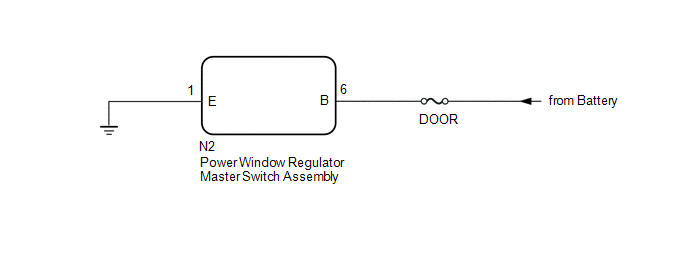
PROCEDURE
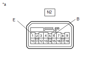
(a) Disconnect the N2 master switch connector. (b) Measure the voltage according to the value(s) in the table below. Standard Voltage:
(c) Measure the resistance according to the value(s) in the table below. Standard Resistance:
|
Toyota Tundra Service Manual > Sfi System: Throttle / Pedal Position Sensor / Switch "D" Circuit (P2120,P2122,P2123,P2125,P2127,P2128,P2138)
DESCRIPTION The accelerator pedal position sensor is mounted on the accelerator pedal bracket and has 2 sensor circuits: VPA (main) and VPA2 (sub). This sensor is a non-contact type and uses Hall-effect elements in order to yield accurate signals even in extreme driving conditions, such as at high s ...


