Toyota Tundra Service Manual: Rear Window Defogger System does not Operate

Toyota Tundra Service Manual / Vehicle Interior / Window / Glass / Window Defogger System / Rear Window Defogger System does not Operate

DESCRIPTION

When the air conditioning control assembly (rear window defogger switch) is turned on, a rear window defogger activation request signal is sent via the LIN communication line to the air conditioning amplifier. Then the air conditioning amplifier operates the rear window defogger.

WIRING DIAGRAM

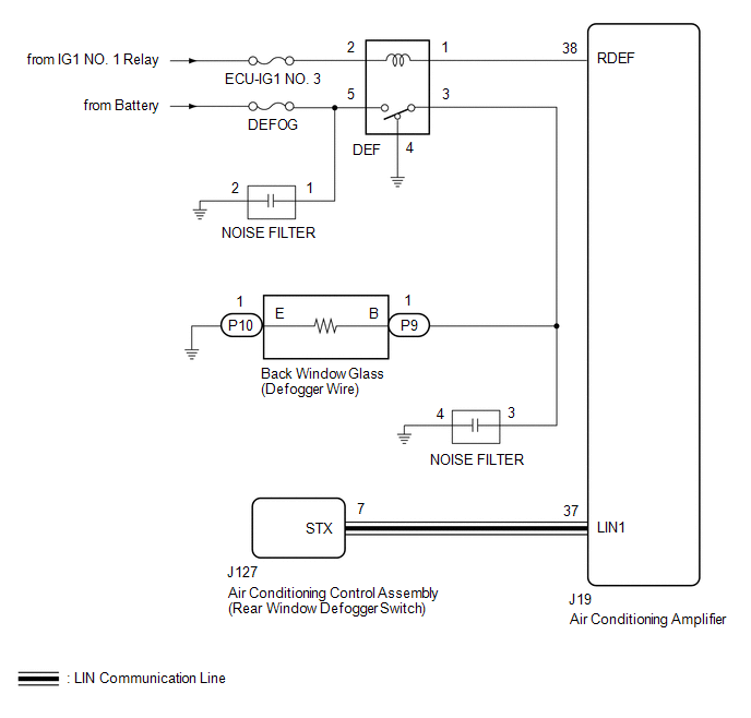
CAUTION / NOTICE / HINT

HINT:

This circuit uses the LIN communication line. Before performing the inspection, check that the LIN communication system is functioning normally (see page ).

NOTICE:

Inspect the fuses for circuits related to this system before performing the following procedure.

PROCEDURE

1.

PERFORM ACTIVE TEST USING TECHSTREAM (DEFOGGER RELAY)

(a) Select the Active Test, using the Techstream to generate a control command, and then check that the rear window defogger operates (See page ).

Air Conditioner

Tester Display

Test Part

Control Range

Diagnostic Note

Defogger Relay (Rear)

Defogger relay

ON or OFF

-

OK:

Rear window defogger operates normally.

NG

GO TO STEP 3

OK

2.

CHECK AIR CONDITIONING CONTROL ASSEMBLY

(a) Temporarily replace the air conditioning control assembly with a new or normally functioning one (See page ).

(b) Check that the malfunction disappears.

OK:

Malfunction disappears.

OK

END (AIR CONDITIONING CONTROL ASSEMBLY IS DEFECTIVE)

NG

REPLACE AIR CONDITIONING AMPLIFIER

3.

INSPECT DEFOGGER RELAY (DEF)

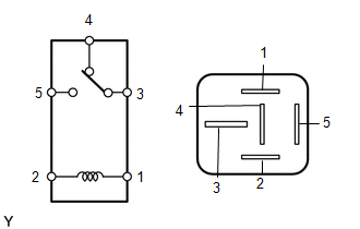
(a) Remove the defogger relay (DEF) from the engine room relay block, junction block.

(b) Measure the resistance according to the value(s) in the table below.

Standard Resistance:

Tester Connection

Condition

Specified Condition

3 - 4

When battery voltage is not applied between terminals 1 and 2

Below 1 Ω

3 - 5

10 kΩ or higher

3 - 4

When battery voltage is applied to terminals 1 and 2

10 kΩ or higher

3 - 5

Below 1 Ω

NG

REPLACE DEFOGGER RELAY

OK

4.

CHECK HARNESS AND CONNECTOR (DEFOGGER RELAY - BATTERY AND AIR CONDITIONING AMPLIFIER)

*a

Component without relay connected

(Engine Room Relay Block, Junction Block)

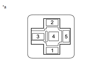
(a) Remove the defogger relay (DEF) from the engine room relay block, junction block.

(b) Disconnect the J19 air conditioning amplifier connector.

(c) Measure the voltage according to the value(s) in the table below.

Standard Voltage:

Tester Connection

Condition

Specified Condition

Defogger relay (DEF) terminal 2 - Body ground

Ignition switch ON

11 to 14 V

Ignition switch OFF

Below 1 V

Defogger relay (DEF) terminal 5 - Body ground

Always

11 to 14 V

(d) Measure the resistance according to the value(s) in the table below.

Standard Resistance:

Tester Connection

Condition

Specified Condition

Defogger relay (DEF) terminal 1 - J19-38 (RDEF)

Always

Below 1 Ω

Defogger relay (DEF) terminal 1 or J19-38 (RDEF) - Body ground

Always

10 kΩ or higher

NG

REPAIR OR REPLACE HARNESS OR CONNECTOR

OK

5.

CHECK HARNESS AND CONNECTOR (DEFOGGER WIRE - DEFOGGER RELAY AND BODY GROUND)

(a) Disconnect the P9 and P10 rear window glass (defogger wire) connectors.

(b) Remove the defogger relay (DEF) from the engine room relay block, junction block.

(c) Measure the resistance according to the value(s) in the table below.

Standard Resistance:

Tester Connection

Condition

Specified Condition

P9-1 (B) - Defogger relay (DEF) terminal 3

Always

Below 1 Ω

P10-1 (E) - Body ground

Always

Below 1 Ω

Defogger relay (DEF) terminal 4 - Body ground

Always

Below 1 Ω

P9-1 (B) or Defogger relay (DEF) terminal 3 - Body ground

Always

10 kΩ or higher

NG

REPAIR OR REPLACE HARNESS OR CONNECTOR

OK

6.

CHECK BACK WINDOW GLASS (DEFOGGER WIRE)

(a) Perform the on-vehicle inspection, check that the window defogger system operates normally (See page ).

OK:

Malfunction disappears.

OK

REPLACE AIR CONDITIONING AMPLIFIER

NG

REPAIR DEFOGGER WIRE

    Problem Symptoms Table

    System Description

    See More:

    Toyota Tundra Service Manual > Occupant Classification System: Front Occupant Classification Sensor RH Circuit Malfunction (B1781)
    DESCRIPTION The front occupant detection sensor RH circuit consists of the occupant classification ECU and the front occupant detection sensor RH. DTC B1781 is set when a malfunction is detected in the front occupant detection sensor RH circuit. DTC Code DTC Detection Condition Trouble Area B1781 On ...

    Toyota Tundra Owners Manual

    Toyota Tundra Service Manual

    © 2024 Copyright www.ttundra.com
    0.0323