Toyota Tundra Service Manual: LVDS Signal Malfunction (from Extension Module) (B1532,B156C)

Toyota Tundra Service Manual / Audio, Visual, Telematics / Navigation / Multi Info Display / Navigation System / LVDS Signal Malfunction (from Extension Module) (B1532,B156C)

DESCRIPTION

DTC Code

DTC Detection Condition

Trouble Area

B1532

When either condition below is met:

  • Video signal (digital) is lost.
  • The stereo component tuner assembly is not connected while the ignition switch is ON or ACC.
  • Communication between the navigation receiver assembly and the stereo component tuner assembly is not possible when the engine is started.
  • No. 1 navigation wire
  • Stereo component tuner assembly
  • Navigation receiver assembly
  • Harness or connector

B156C

WIRING DIAGRAM

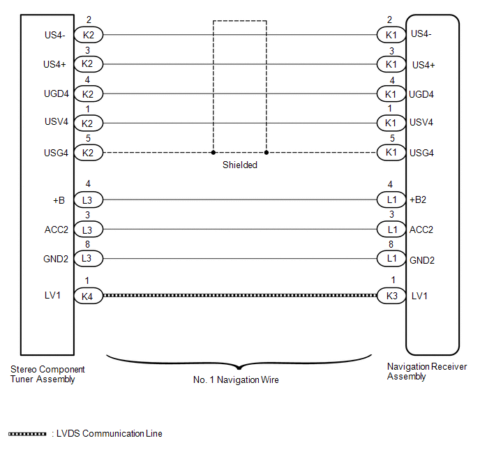
CAUTION / NOTICE / HINT

NOTICE:

After replacing the stereo component tuner assembly of vehicles subscribed to pay-type satellite radio broadcasts, XM radio ID registration is necessary.

PROCEDURE

1.

CHECK FOR DTC

(a) Clear the DTCs (See page ).

(b) Check for DTCs (See page ).

OK:

No DTCs are output.

OK

USE SIMULATION METHOD TO CHECK

NG

2.

CHECK HARNESS AND CONNECTOR (NAVIGATION RECEIVER ASSEMBLY - STEREO COMPONENT TUNER ASSEMBLY)

(a) Disconnect the K1 and L1 navigation receiver assembly connectors.

(b) Disconnect the K2 and L3 stereo component tuner assembly connector.

(c) Measure the resistance according to the value(s) in the table below.

Standard Resistance:

Tester Connection

Condition

Specified Condition

K1-1 (USV4) - K2-1 (USV4)

Always

Below 1 Ω

K1-2 (US4-) - K2-2 (US4-)

Always

Below 1 Ω

K1-3 (US4+) - K2-3 (US4+)

Always

Below 1 Ω

K1-4 (UGD4) - K2-4 (UGD4)

Always

Below 1 Ω

K1-5 (USG4) - K2-5 (USG4)

Always

Below 1 Ω

L1-4 (+B2) - L3-4 (+B)

Always

Below 1 Ω

L1-3 (ACC2) - L3-3 (ACC2)

Always

Below 1 Ω

L1-8 (GND2) - L3-8 (GND2)

Always

Below 1 Ω

K1-1 (USV4) - Body ground

Always

10 kΩ or higher

K1-2 (US4-) - Body ground

Always

10 kΩ or higher

K1-3 (US4+) - Body ground

Always

10 kΩ or higher

K1-4 (UGD4) - Body ground

Always

10 kΩ or higher

K1-5 (USG4) - Body ground

Always

10 kΩ or higher

L1-4 (+B2) - Body ground

Always

10 kΩ or higher

L1-3 (ACC2) - Body ground

Always

10 kΩ or higher

L1-8 (GND2) - Body ground

Always

10 kΩ or higher

NG

REPAIR OR REPLACE HARNESS OR CONNECTOR

OK

3.

CHECK NO. 1 NAVIGATION WIRE

(a) Replace the No. 1 navigation wire with a known good one.

for Column Shift Type: See page

for Floor Shift Type: See page

(b) Clear the DTCs (See page ).

(c) Check for DTCs (See page ).

OK:

No DTCs are output.

OK

END (NO. 1 NAVIGATION WIRE IS DEFECTIVE)

NG

4.

CHECK STEREO COMPONENT TUNER ASSEMBLY

(a) Replace the stereo component tuner assembly with a known good one.

for Column Shift Type: See page

for Floor Shift Type: See page

(b) Clear the DTCs (See page ).

(c) Check for DTCs (See page ).

OK:

No DTCs are output.

Result

Result

Proceed to

OK

A

NG (for Column Shift Type)

B

NG (for Floor Shift Type)

C

A

END (STEREO COMPONENT TUNER ASSEMBLY IS DEFECTIVE)

B

REPLACE NAVIGATION RECEIVER ASSEMBLY

C

REPLACE NAVIGATION RECEIVER ASSEMBLY

    Lost Communication with Meter (B1324)

    HD Radio Tuner Malfunction (B1551,B15A0,B15AD,B15B0,B15B3,B15B4,B15B7)

    See More:

    Toyota Tundra Service Manual > Vehicle Stability Control System: Diagnostic Trouble Code Chart
    DIAGNOSTIC TROUBLE CODE CHART Vehicle Stability Control System DTC No. Detection Item Link C1201 Engine Control System Malfunction C1225 SM Solenoid Circuit C1226 SA2 Solenoid Circuit C1227 SA3 Solenoid Circuit C1228 STR Solenoid Circuit C1234 Yaw Rate Sensor C1237 Speed Sensor Rotor Faulty C1241 Lo ...

    Toyota Tundra Owners Manual

    Toyota Tundra Service Manual

    © 2026 Copyright www.ttundra.com
    0.0127