DESCRIPTION This circuit includes the parking brake switch assembly and navigation receiver assembly. WIRING DIAGRAM 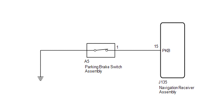 PROCEDURE
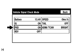
(b) Check that the display changes between ON and OFF according to the parking brake operation. OK:
HINT: This display is updated once per second. As a result, it is normal for the display to lag behind the actual parking brake operation.
(a) Disconnect the J135 navigation receiver assembly connector. (b) Disconnect the A5 parking brake switch assembly connector. (c) Measure the resistance according to the value(s) in the table below. Standard Resistance:
(a) Remove the parking brake switch assembly (See page
(b) Inspect the parking brake switch assembly (See page
|
Toyota Tundra Service Manual > Airbag System: Terminals Of Ecu
TERMINALS OF ECU AIRBAG SENSOR ASSEMBLY Terminal No. Terminal Symbol Destination J177-1 P2+ Instrument panel passenger without door airbag assembly (front passenger side squib 2nd step) J177-2 P2- Instrument panel passenger without door airbag assembly (front passenger side squib 2nd step) J177-3 P- ...

 ).
).