PROCEDURE |
1. | CHECK IF RADIO AUTO-SEARCH FUNCTIONS PROPERLY |
(a) Check the radio automatic station search function by activating it.
OK: Automatic station search function stops on a station.
| OK |
 | USE SIMULATION METHOD TO CHECK |
|
NG |
 | |
| 2. |
CHECK OPTIONAL COMPONENTS | (a)
Check if any optional components that may decrease reception capacity,
such as sunshade film or a telephone antenna, are installed. OK: Optional components are installed.
NOTICE: Do not remove optional components without permission of the customer.
| OK |
| REMOVE OPTIONAL COMPONENTS AND CHECK AGAIN (SEE NOTICE ABOVE) |
|
NG | |
| |
(a) Remove the pull top antenna pole sub-assembly from the fender antenna assembly.
(b) Place the tip of a screwdriver on the antenna and check that noise is heard from the speakers.
OK: Noise occurs. Result |
Result | Proceed to | |
OK (for Column Shift Type) |
A | | OK (for Floor Shift Type) |
B | | NG |
C |
| A |
| REPLACE NAVIGATION RECEIVER ASSEMBLY |
| B |
| REPLACE NAVIGATION RECEIVER ASSEMBLY |
|
C | |
| |
| 4. |
CHECK NAVIGATION RECEIVER ASSEMBLY (ANTENNA) |
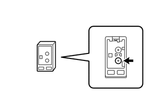
| (a) Remove the antenna connector from the navigation receiver assembly. |
|
(b) Turn the ignition switch to ACC with the navigation receiver assembly connector connected.
(c) Turn on the radio and turn into AM mode. (d)
Place a screwdriver, thin wire or other metal object on the navigation
receiver assembly antenna jack and check that noise can be heard from
the speakers. OK: Noise occurs. Result |
Result | Proceed to | |
OK | A | |
NG (for Column Shift Type) |
B | | NG (for Floor Shift Type) |
C |
| B |
| REPLACE NAVIGATION RECEIVER ASSEMBLY |
| C |
| REPLACE NAVIGATION RECEIVER ASSEMBLY |
|
A | |
| |
| 5. |
INSPECT NAVIGATION RECEIVER ASSEMBLY |
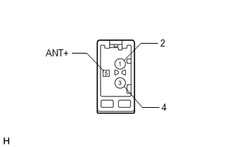
| (a) Disconnect the J151 navigation receiver assembly connector. |
|
(b) Measure the voltage according to the value(s) in the table below. Standard Voltage: |
Tester Connection | Switch Condition |
Specified Condition | |
5 (ANT+) - Body ground |
Ignition switch ACC, radio switch on and FM or AM selected |
11 to 14 V | Result |
Result | Proceed to | |
OK | A | |
NG (for Column Shift Type) |
B | | NG (for Floor Shift Type) |
C |
| B |
| REPLACE NAVIGATION RECEIVER ASSEMBLY |
| C |
| REPLACE NAVIGATION RECEIVER ASSEMBLY |
|
A | |
| |
| 6. |
CHECK PULL TOP ANTENNA POLE SUB-ASSEMBLY |
(a) Check that the pull top antenna pole sub-assembly is securely installed (See page
 ). ). OK: The pull top antenna pole sub-assembly is installed properly.
| NG |
| REINSTALL PULL TOP ANTENNA POLE SUB-ASSEMBLY |
|
OK | |
| |
| 7. |
CHECK FENDER ANTENNA ASSEMBLY | (a) Replace the fender antenna assembly and check if radio broadcasts can be received normally (See page
). OK: Radio broadcasts can be received normally. Result |
Result | Proceed to | |
OK | A | |
NG (for Column Shift Type) |
B | | NG (for Floor Shift Type) |
C |
| A |
| END (FENDER ANTENNA ASSEMBLY IS DEFECTIVE) |
| B |
| REPLACE NAVIGATION RECEIVER ASSEMBLY |
| C |
| REPLACE NAVIGATION RECEIVER ASSEMBLY | |