Toyota Tundra Service Manual: Short to +B in Outer Mirror Indicator(Master) (C1AB0)

DESCRIPTION

This DTC is stored when the blind spot monitor sensor RH detects a short to +B in the outer rear view mirror indicator RH.

DTC No.

DTC Detection Condition

Trouble Area

C1AB0

Both of the following conditions are met:
  • The blind spot monitor system is on
  • The blind spot monitor sensor is not sending voltage to the indicator but the indicator receives voltage above a specified level for a specified period of time
  • Outer rear view mirror sub-assembly RH
  • Outer rear view mirror assembly RH
  • Harness or connector
  • Blind spot monitor sensor RH

WIRING DIAGRAM

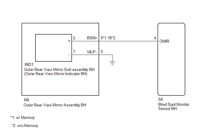
CAUTION / NOTICE / HINT

NOTICE:

When checking for DTCs, make sure that the blind spot monitor system is turned on.

PROCEDURE

1.

CHECK DTC

(a) Clear the DTCs.

Click here

(b) Recheck for DTCs and check if the same DTC is output again.

Click here

OK:

No DTCs are output.

OK

USE SIMULATION METHOD TO CHECK

NG

2.

CHECK HARNESS AND CONNECTOR (OUTER REAR VIEW MIRROR INDICATOR CIRCUIT)

(a) Disconnect the blind spot monitor sensor RH connector.

*a

Front view of wire harness connector

(to Blind Spot Monitor Sensor RH)

(b) Measure the voltage according to the value(s) in the table below.

Standard Voltage:

Tester Connection

Switch Condition

Specified Condition

S6-4 (OMIR) - Body ground

Ignition switch ON

Below 1 V

OK

REPLACE BLIND SPOT MONITOR SENSOR RH

NG

3.

CHECK HARNESS AND CONNECTOR (OUTER REAR VIEW MIRROR INDICATOR CIRCUIT)

(a) Disconnect the S6 blind spot monitor sensor RH connector.

*a

Front view of wire harness connector

(to Blind Spot Monitor Sensor RH)

(b) Disconnect the IND1 outer rear view mirror sub-assembly RH connector.

(c) Measure the voltage according to the value(s) in the table below.

Standard Voltage:

Tester Connection

Switch Condition

Specified Condition

S6-4 (OMIR) - Body ground

Ignition switch ON

Below 1 V

OK

REPLACE OUTER REAR VIEW MIRROR SUB-ASSEMBLY RH

NG

4.

CHECK HARNESS AND CONNECTOR (OUTER REAR VIEW MIRROR INDICATOR CIRCUIT)

(a) Disconnect the S6 blind spot monitor sensor RH connector.

*a

Front view of wire harness connector

(to Blind Spot Monitor Sensor RH)

(b) Disconnect the M6 outer rear mirror assembly RH connector.

(c) Measure the voltage according to the value(s) in the table below.

Standard Voltage:

Tester Connection

Switch Condition

Specified Condition

S6-4 (OMIR) - Body ground

Ignition switch ON

Below 1 V

OK

REPLACE OUTER REAR VIEW MIRROR ASSEMBLY RH

NG

REPAIR OR REPLACE HARNESS OR CONNECTOR

    Steering Angle Sensor (C1A47)

    Short to +B in Outer Mirror Indicator(Slave) (C1AB1)

    See More:

    Toyota Tundra Service Manual > Sfi System: Readiness Monitor Drive Pattern
    READINESS MONITOR DRIVE PATTERN 1. PURPOSE OF READINESS TESTS The On-Board Diagnostic (OBD II) system is designed to monitor the performance of emission related components, and indicate any detected abnormalities with DTCs (Diagnostic Trouble Codes). Since various components need to be monitored dur ...

    Toyota Tundra Owners Manual

    Toyota Tundra Service Manual

    © 2024 Copyright www.ttundra.com
    0.0125