WIRING DIAGRAM 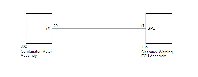 PROCEDURE
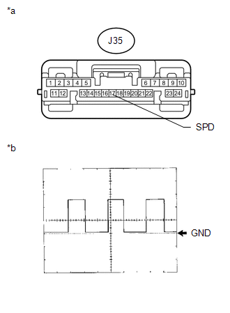
(b) Using an oscilloscope, check the signal waveform of the combination meter assembly. Measurement Condition
OK: Refer to the illustration. HINT: As the vehicle speed increases, the wave length shortens. Text in Illustration
(a) Disconnect the J35 clearance warning ECU assembly connector. (b) Disconnect the J28 combination meter assembly connector. (c) Measure the resistance according to the value(s) in the table below. Standard Resistance:
|
Toyota Tundra Owners Manual > Toyota Tundra Owners Manual: Pictorial index
Exterior Side doors Locking/unlocking Opening/closing the door glasses Warning messages Tailgate Locking/unlocking Opening/closing the tailgate Removing the tailgate Outside rear view mirrors Adjusting the mirror angle Folding the mirrors Driving position memory*1 Defogging the mirrors*2 Windshield ...