Toyota Tundra Service Manual: Image from Camera for Rear View Monitor is Abnormal

DESCRIPTION

This is the display signal circuit between the navigation receiver assembly and the television camera assembly.

WIRING DIAGRAM
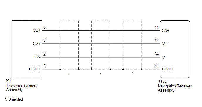
PROCEDURE

1.

CHECK HARNESS AND CONNECTOR (NAVIGATION RECEIVER ASSEMBLY - TELEVISION CAMERA ASSEMBLY)

NG

REPAIR OR REPLACE HARNESS OR CONNECTOR

OK

2.

CHECK NAVIGATION RECEIVER ASSEMBLY

B

REPLACE NAVIGATION RECEIVER ASSEMBLY

C

REPLACE NAVIGATION RECEIVER ASSEMBLY

A

3.

CHECK NAVIGATION RECEIVER ASSEMBLY

B

REPLACE NAVIGATION RECEIVER ASSEMBLY

C

REPLACE NAVIGATION RECEIVER ASSEMBLY

A

4.

CHECK TELEVISION CAMERA ASSEMBLY

OK

PROCEED TO NEXT SUSPECTED AREA SHOWN IN PROBLEM SYMPTOMS TABLE

NG

REPLACE TELEVISION CAMERA ASSEMBLY

    How To Proceed With Troubleshooting

    Parts Location

    See More:

    Toyota Tundra Service Manual > Audio And Visual System: Operation Check
    OPERATION CHECK 1. CHECK PANEL & STEERING SWITCH HINT: The radio and display receiver assembly panel switches are checked in the following procedure. Illustrations may differ from the actual vehicle screen depending on the device settings and options. Therefore, some detailed areas may not be ex ...

    Toyota Tundra Owners Manual

    Toyota Tundra Service Manual

    © 2025 Copyright www.ttundra.com
    0.0104