Toyota Tundra Service Manual: Image from Camera for Rear View Monitor is Abnormal

DESCRIPTION

This is the display signal circuit between the radio and display receiver assembly and the television camera assembly.

WIRING DIAGRAM
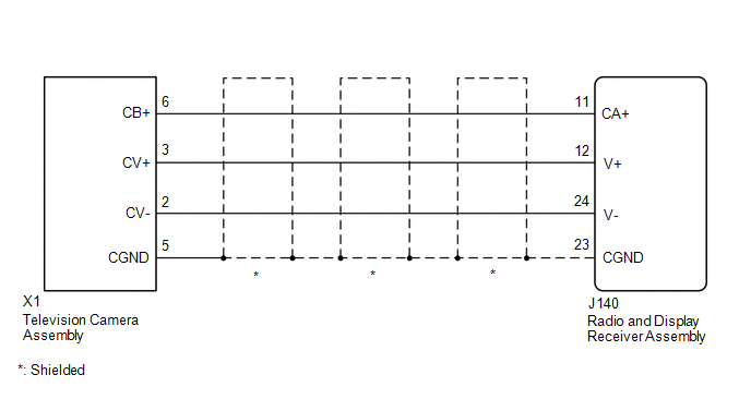
PROCEDURE

1.

CHECK HARNESS AND CONNECTOR (RADIO AND DISPLAY RECEIVER ASSEMBLY - TELEVISION CAMERA ASSEMBLY)

NG

REPAIR OR REPLACE HARNESS OR CONNECTOR

OK

2.

CHECK RADIO AND DISPLAY RECEIVER ASSEMBLY

B

REPLACE RADIO AND DISPLAY RECEIVER ASSEMBLY

C

REPLACE RADIO AND DISPLAY RECEIVER ASSEMBLY

A

3.

CHECK RADIO AND DISPLAY RECEIVER ASSEMBLY

B

REPLACE RADIO AND DISPLAY RECEIVER ASSEMBLY

C

REPLACE RADIO AND DISPLAY RECEIVER ASSEMBLY

A

4.

CHECK TELEVISION CAMERA ASSEMBLY

OK

PROCEED TO NEXT SUSPECTED AREA SHOWN IN PROBLEM SYMPTOMS TABLE

NG

REPLACE TELEVISION CAMERA ASSEMBLY

    How To Proceed With Troubleshooting

    Parts Location

    See More:

    Toyota Tundra Service Manual > Sfi System: ACIS Control Circuit
    DESCRIPTION This circuit opens and closes the Intake Air Control Valve (IACV) in response to the engine load in order to increase the intake efficiency (ACIS: Acoustic Control Induction System). WIRING DIAGRAM PROCEDURE 1. PERFORM ACTIVE TEST USING TECHSTREAM (OPERATE VSV FOR ACIS) (a) Disconnect th ...

    Toyota Tundra Owners Manual

    Toyota Tundra Service Manual

    © 2026 Copyright www.ttundra.com
    0.0166