INSPECTION PROCEDURE 1. INSPECT NO. 2 ULTRASONIC SENSOR
2. INSPECT NO. 3 ULTRASONIC SENSOR
|
Toyota Tundra Service Manual > Power Tilt And Power Telescopic Steering Column System: Terminals Of Ecu
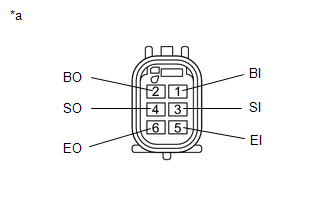
TERMINALS OF ECU MULTIPLEX TILT AND TELESCOPIC ECU *a Component without harness connected (Multiplex Tilt and Telescopic ECU) - - (a) Measure the voltage and resistance according to the value(s) in the table below. Terminal No. (Symbol) Wiring Color Terminal Description Condition Specified Condition ...