REMOVAL CAUTION / NOTICE / HINT CAUTION: As the rear bumper cover is extremely heavy, the engine lifter may suddenly drop if the instructions listed in the repair manual are not followed. Therefore, always follow the instructions listed in the repair manual when performing this procedure. PROCEDURE 1. REMOVE CONNECTOR COVER (for Steel Type Bumper)
2. REMOVE CONNECTOR COVER (for Resin Type Bumper) 3. REMOVE WIRING HARNESS CONNECTOR (for Steel Type Bumper) 4. REMOVE WIRING HARNESS CONNECTOR (for Resin Type Bumper) 5. REMOVE REAR BUMPER COVER (for Steel Type Bumper) 6. REMOVE REAR BUMPER COVER (for Resin Type Bumper) 7. REMOVE REAR BUMPER PLATE LH (for Steel Type Bumper) 8. REMOVE REAR BUMPER PLATE LH (for Resin Type Bumper) 9. REMOVE REAR BUMPER PLATE RH (for Steel Type Bumper) 10. REMOVE REAR BUMPER PLATE RH (for Resin Type Bumper) 11. REMOVE REAR BUMPER PAD SUB-ASSEMBLY (for Steel Type Bumper) 12. REMOVE REAR BUMPER PAD SUB-ASSEMBLY (for Resin Type Bumper) 13. REMOVE LICENSE PLATE LIGHT ASSEMBLY LH 14. REMOVE LICENSE PLATE LIGHT ASSEMBLY RH HINT: Use the same procedure described for the LH side. 15. REMOVE REAR BUMPER EXTENSION INSERT LH (for Resin Type Bumper) 16. REMOVE REAR BUMPER EXTENSION INSERT RH (for Resin Type Bumper) 17. REMOVE REAR BUMPER BAR CORNER REINFORCEMENT LH (for Steel Type Bumper) 18. REMOVE REAR BUMPER BAR CORNER REINFORCEMENT RH (for Steel Type Bumper) 19. REMOVE NO. 2 FRAME WIRE (for Steel Type Bumper) 20. REMOVE NO. 2 ULTRASONIC SENSOR RETAINER (for Steel Type Bumper)
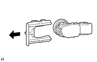
21. REMOVE NO. 2 ULTRASONIC SENSOR (for Steel Type Bumper)
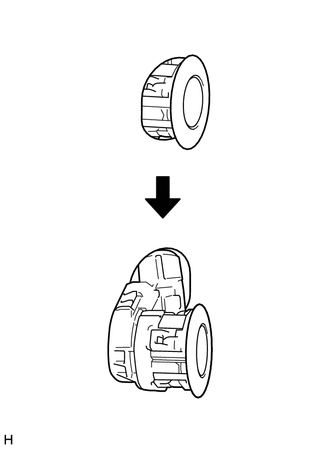
22. REMOVE NO. 2 ULTRASONIC SENSOR (for Resin Type Bumper) (a) Detach the 4 claws and remove the No. 2 ultrasonic sensor as shown in the illustration. 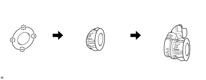 HINT: The illustration shows the No. 2 ultrasonic sensor for the RH. The horizontal orientation of the No. 2 ultrasonic sensor for the LH is opposite that of the image shown in the illustration. 23. REMOVE NO. 3 ULTRASONIC SENSOR (a) Detach the 4 claws and remove the No. 3 ultrasonic sensor as shown in the illustration. HINT: The illustration shows the No. 3 ultrasonic sensor for the RH. The horizontal orientation of the No. 3 ultrasonic sensor for the LH is opposite that of the image shown in the illustration. |