DESCRIPTION If a malfunction is detected in the power supply circuit, the trailer brake control ECU (brake control with bracket relay) stores this DTC.
WIRING DIAGRAM 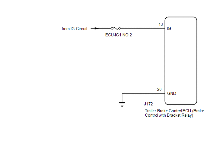 CAUTION / NOTICE / HINT NOTICE: Inspect the fuses for circuits related to this system before performing the following procedure. PROCEDURE
(a) Check the battery voltage. Standard Voltage:
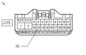
(b) Disconnect the J172 trailer brake control ECU (brake control with bracket relay) connector. (c) Inspect both the connector case and the terminal for deformation and corrosion. OK: No deformation or corrosion. (d) Turn the ignition switch to ON. (e) Measure the voltage according to the value(s) in the table below. Standard Voltage:
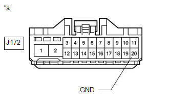
(b) Measure the resistance according to the value(s) in the table below. Standard Resistance:
(a) Reconnect the J172 trailer brake control ECU (brake control with bracket relay) connector. (b) Clear the DTCs. Click here (c) Turn the ignition switch off. (d) Turn the ignition switch to ON. (e) Perform a road test. (f) Check if the same DTC is output. Click here
|
Toyota Tundra Owners Manual > Instrument cluster: Multi-information display
Display contents The multi-information display presents the driver with a variety of vehicle data. Menu icons Displays the following information when an icon is selected. Some of the information may be displayed automatically depending on the situation. Drive information Select to display various dr ...