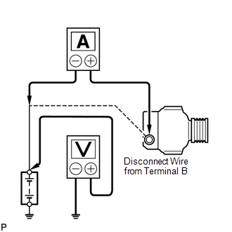
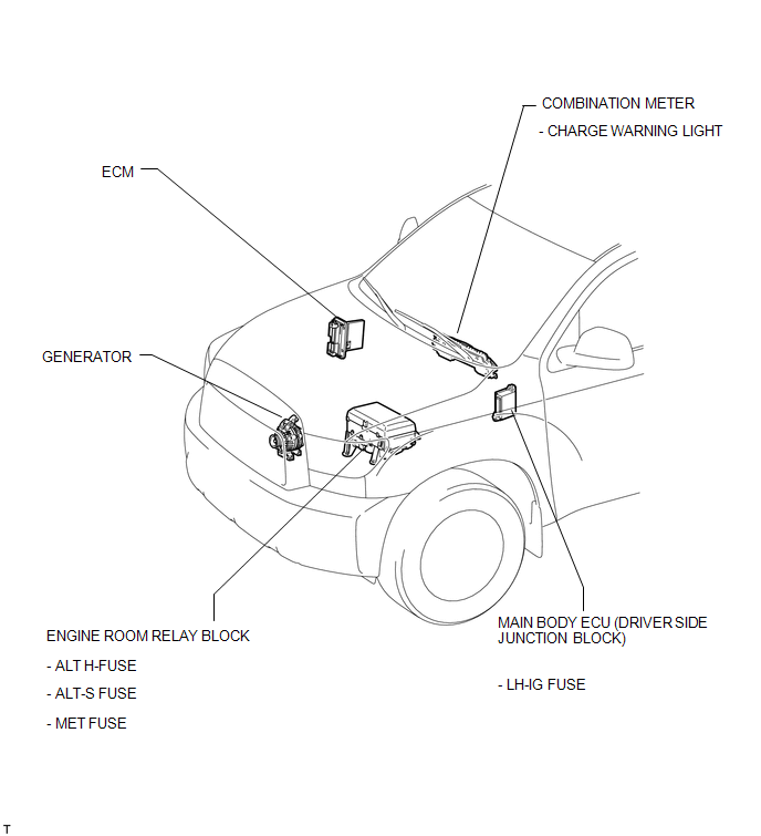
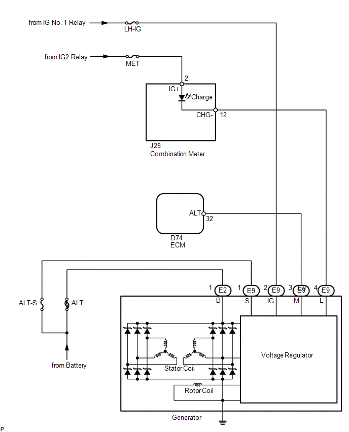
On-vehicle Inspection ON-VEHICLE INSPECTION PROCEDURE 1. CHECK BATTERY CONDITION NOTICE: If the battery is weak or if the engine is difficult to start, perform the following procedures. (a) Check the battery for damage and deformation. If severe damage, deformation or leakage is found, replace the battery. (b) Check the electrolyte quantity of each cell. (1) For maintenance-free batteries:
(2) For non-maintenance-free batteries:
(c) Turn the ignition switch off and turn on the headlight for 20 to 30 seconds. This will remove the surface charge from the battery.
2. INSPECT BATTERY TERMINAL AND FUSE (a) Visually check the battery terminals. (1) Check that the battery terminals are not loose or corroded. Torque: Positive (+) battery terminal : 5.9 N·m {60 kgf·cm, 52 in·lbf} Negative (-) battery terminal : 5.9 N·m {60 kgf·cm, 52 in·lbf} (b) Check the H-fuse and fuses. (1) Measure the resistance according to the value(s) in the table below. Standard resistance:
If the result is not as specified, replace the fuse as necessary. 3. INSPECT FAN AND GENERATOR V BELT 4. INSPECT GENERATOR WIRING (a) Visually check the generator wiring. (1) Check that the wiring is in good condition. 5. CHECK FOR ABNORMAL NOISES (a) Listen for abnormal noises from the generator. (1) Check that no abnormal noises are heard from the generator while the engine is running. 6. INSPECT CHARGE WARNING LIGHT CIRCUIT (a) Turn the ignition switch to ON. Check that the charge warning light comes on. (b) Start the engine and check that the light goes off. If the light does not operate as specified, troubleshoot the charge warning light circuit. 7. INSPECT CHARGING CIRCUIT WITHOUT LOAD  (a) Connect a voltmeter and ammeter to the charging circuit as follows. (1) Disconnect the wire from terminal B of the generator, then connect it to the negative (-) lead of an ammeter. (2) Connect the positive (+) lead of the ammeter to terminal B of the generator. (3) Connect the positive (+) lead of a voltmeter to the positive (+) terminal of the battery. (4) Ground the negative (-) lead of the voltmeter. (b) Check the charging circuit. (1) Keep the engine speed at 2000 rpm and check the reading on the ammeter and voltmeter. Standard current: 10 A or less Standard voltage: 13.2 to 14.8 V If the voltmeter reading is higher than the standard voltage, replace the voltage regulator. HINT: If the battery is not fully charged, the ammeter reading will sometimes be higher than the standard current. 8. INSPECT CHARGING CIRCUIT WITH LOAD (a) With the engine running at 2000 rpm, turn the high beam headlights ON and turn the heater blower switch to the "HI" position. (b) Check the reading on the ammeter. Standard current: 30 A or higher If the ammeter reading is below the standard current, repair the generator. HINT: If the battery is fully charged, the indication will sometimes be below the standard current. If this is the case, add more electrical load (operate the wipers, rear window defogger, etc.) and check the reading on the ammeter again. Parts Location PARTS LOCATION ILLUSTRATION  Precaution PRECAUTION 1. PRECAUTION (a) Check that the battery cables are connected to the correct terminals. (b) Disconnect the battery cables when the battery is given a quick charge. (c) Do not perform tests with a high voltage insulation resistance tester. (d) Never disconnect the battery while the engine is running. (e) Check that the charging cable nut is securely installed to terminal B of the generator and the fuse box. System Diagram SYSTEM DIAGRAM  |
Toyota Tundra Service Manual > Rear View Monitor System(for Radio And Display Type): Problem Symptoms Table
PROBLEM SYMPTOMS TABLE HINT: Use the table below to help determine the cause of problem symptoms. If multiple suspected areas are listed, the potential causes of the symptoms are listed in order of probability in the "Suspected Area" column of the table. Check each symptom by checking the suspected ...