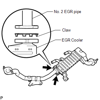
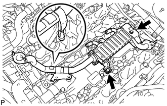
Components COMPONENTS ILLUSTRATION 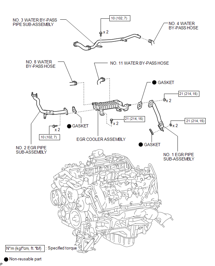 Installation INSTALLATION PROCEDURE 1. INSTALL NO. 2 EGR PIPE SUB-ASSEMBLY
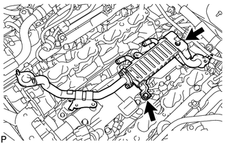
2. INSTALL EGR COOLER ASSEMBLY
3. INSTALL NO. 1 EGR PIPE SUB-ASSEMBLY
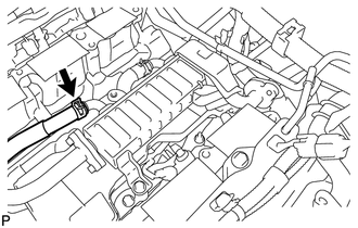
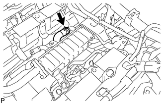
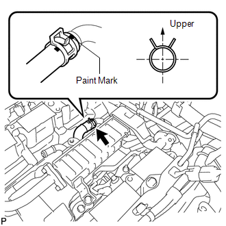
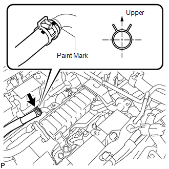
4. CONNECT NO. 11 WATER BY-PASS HOSE
5. CONNECT NO. 8 WATER BY-PASS HOSE
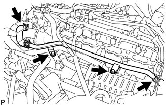
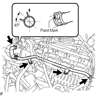
6. INSTALL NO. 3 WATER BY-PASS PIPE SUB-ASSEMBLY
(b) Connect the No. 4 water by-pass hose. 7. INSTALL INTAKE MANIFOLD ASSEMBLY (a) Install the intake manifold (See page Removal REMOVAL PROCEDURE 1. REMOVE INTAKE MANIFOLD ASSEMBLY (a) Remove the intake manifold (See page
2. REMOVE NO. 3 WATER BY-PASS PIPE SUB-ASSEMBLY
(b) Disconnect the hose and remove the 2 bolts and No. 3 water by-pass pipe. 3. DISCONNECT NO. 8 WATER BY-PASS HOSE
4. DISCONNECT NO. 11 WATER BY-PASS HOSE
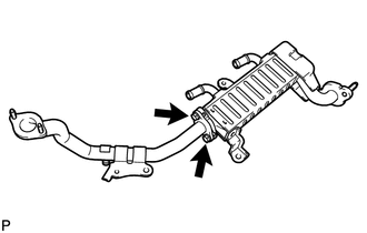
5. REMOVE NO. 1 EGR PIPE SUB-ASSEMBLY 6. REMOVE EGR COOLER ASSEMBLY
7. REMOVE NO. 2 EGR PIPE SUB-ASSEMBLY
|
Toyota Tundra Service Manual > Front Power Seat Control System(w/ Memory): Terminals Of Ecu
TERMINALS OF ECU 1. CHECK POSITION CONTROL ECU AND SWITCH ASSEMBLY (a) Disconnect the Z9 and Z10 position control ECU and switch assembly connectors. (b) Measure the voltage and resistance according to the value(s) in the table below. Terminal No. (Symbols) Wiring Color Terminal Description Conditio ...


 ).
).