Components COMPONENTS ILLUSTRATION 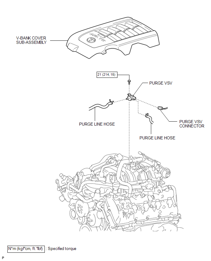 Inspection INSPECTION PROCEDURE 1. INSPECT PURGE VSV 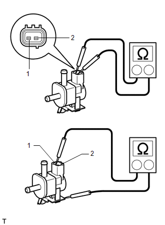 (a) Measure the resistance according to the value(s) in the table below. Standard Resistance:
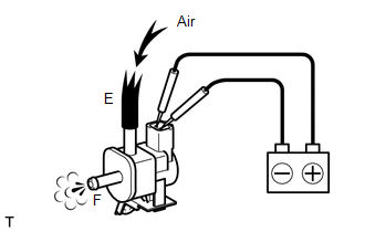
If the result is not as specified, replace the purge VSV. (b) Inspect the purge VSV operation. 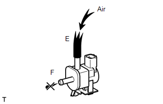 (1) Check that air does not flow from ports.
(3) Check that air flows from ports. If the result is not as specified, replace the purge VSV. Installation INSTALLATION PROCEDURE 1. INSTALL PURGE VSV
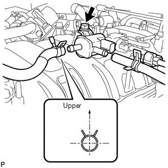
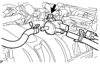
(b) Connect the connector. 2. CONNECT PURGE LINE HOSE (a) Connect the 2 hoses. HINT: Turn the claw of the clip to the upper side. 3. INSTALL V-BANK COVER SUB-ASSEMBLY Removal REMOVAL PROCEDURE 1. REMOVE V-BANK COVER SUB-ASSEMBLY 2. DISCONNECT PURGE LINE HOSE (a) Disconnect the 2 purge line hoses. 3. REMOVE PURGE VSV
(b) Remove the bolt and purge VSV. |
Toyota Tundra Service Manual > Automatic Transmission System: Shift Solenoid "C" Control Circuit Low (Shift Solenoid Valve S3) (P0979,P0980)
DESCRIPTION Shifting from 1st to 6th is performed in combination with ON and OFF operation of the shift solenoid valves SL1, SL2, S1, S2, S3, S4 and SR, which are controlled by the ECM. If an open or short circuit occurs in any of the shift solenoid valves, the ECM controls the remaining normal shif ...