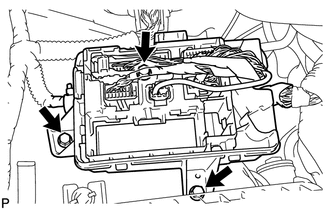
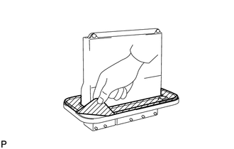
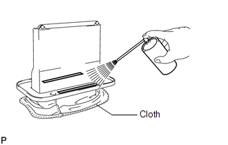
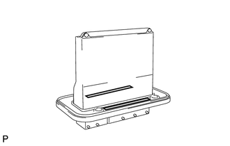
Components COMPONENTS ILLUSTRATION 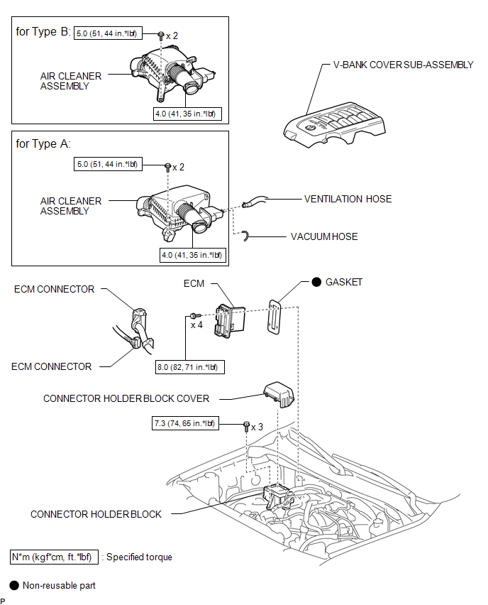 Installation INSTALLATION PROCEDURE 1. INSTALL GASKET (a) Clean the ECM seal's surface with non-residue solvent. (b) Attach a new gasket to the ECM. 2. INSTALL ECM
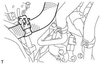
3. CONNECT CONNECTOR HOLDER BLOCK
(b) Install the connector holder block cover. 4. INSTALL AIR CLEANER ASSEMBLY 5. INSTALL V-BANK COVER SUB-ASSEMBLY Removal REMOVAL PROCEDURE 1. REMOVE V-BANK COVER SUB-ASSEMBLY 2. REMOVE AIR CLEANER ASSEMBLY 3. DISCONNECT CONNECTOR HOLDER BLOCK (a) Remove the connector holder block cover.
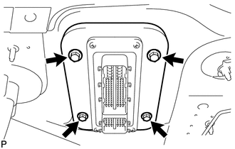
4. REMOVE ECM
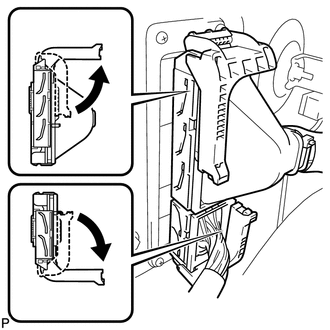
(b) Raise the 2 levers while pushing the locks on the 2 levers shown in the illustration. NOTICE: Make sure that the lock lever is raised 90° as shown in the illustration before disconnecting the connectors. Failure to do this may cause the connectors to break. 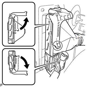 (c) Disconnect the 2 connectors.
5. REMOVE GASKET
|
Toyota Tundra Service Manual > Power Tilt And Power Telescopic Steering Column System: Problem Symptoms Table
PROBLEM SYMPTOMS TABLE HINT: Use the table below to help determine the cause of problem symptoms. If multiple suspected areas are listed, the potential causes of the symptoms are listed in order of probability in the "Suspected Area" column of the table. Check each system by checking the suspected a ...