DESCRIPTION This circuit opens and closes the Intake Air Control Valve (IACV) in response to the engine load in order to increase the intake efficiency (ACIS: Acoustic Control Induction System). 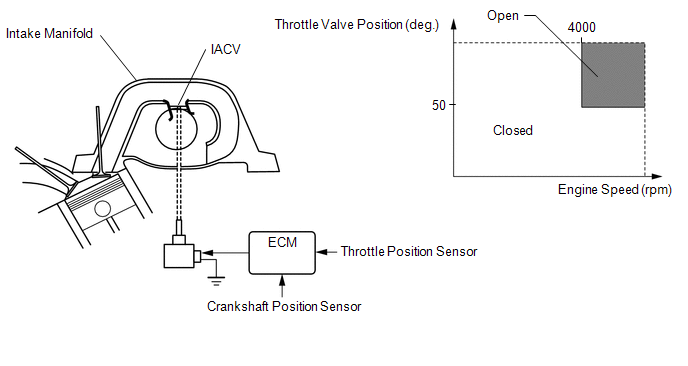 WIRING DIAGRAM  PROCEDURE
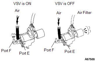 (a) Disconnect the vacuum hose from port F on the vacuum switching valve (for ACIS). (b) Connect the Techstream to the DLC3. (c) Start the engine. (d) Enter the following menus: Powertrain / Engine and ECT / Active Test / Active the VSV for Intake Control. (e) Operate the VSV for ACIS. (f) Check the VSV air flow when switching the VSV. OK:
(a) Inspect the intake air control valve (See page
(a) Inspect the vacuum switching valve (for ACIS) (See page
(a) Remove the EFI NO. 2 fuse from the engine room relay block. (b) Measure the resistance according to the value(s) in the table below. Standard Resistance:
(c) Reinstall the EFI NO. 2 fuse. (d) Disconnect the intake air control valve connector. (e) Disconnect the ECM connector. (f) Remove the integration relay from the engine room relay block. (g) Disconnect the integration relay connector. (h) Measure the resistance according to the value(s) in the table below. Standard Resistance:
|
Toyota Tundra Service Manual > Propeller Shaft Assembly(for 2wd): Reassembly
REASSEMBLY PROCEDURE 1. INSTALL PROPELLER SHAFT UNIVERSAL JOINT SPIDER BEARING HINT: Use the same installation procedure for both the sleeve yoke side and flange yoke side universal joint spider bearings. (a) Apply MP grease to a new spider and 4 new bearings. NOTICE: Be careful not to apply too muc ...


 ).
).
