|
Tester Display | Measurement Item |
Diagnostic Note |
|
Vehicle Speed | Vehicle speed |
Speed indicated on speedometer. |
|
Engine Speed | Engine speed |
- |
| Calculate Load |
Calculated load | Load calculated by ECM. |
|
Vehicle Load | Vehicle load |
- |
| MAF |
Mass air flow volume | If approximately 0.0 gm/sec.:
- Mass air flow meter power source circuit open or shorted.
- VG circuit open or shorted.
If 160.0 gm/sec. or more:
|
| Atmosphere Pressure |
Atmospheric pressure |
- |
| MAP |
Intake manifold pressure |
- |
| Coolant Temp |
Engine coolant temperature | If -40°C (-40°F), sensor circuit open.
If 140°C (284°F) or more, sensor circuit shorted. |
|
Intake Air | Intake air temperature |
If -40°C (-40°F), sensor circuit open. If 140°C (284°F) or more, sensor circuit shorted. |
|
Engine Run Time | Accumulated engine running time |
- |
| Initial Engine Coolant Temp |
Engine coolant temperature at engine start |
- |
| Coolant Temp Variation after Engine Start |
Coolant temp variation after engine start |
- |
| Initial Intake Air Temp |
Intake air temperature at engine start |
- |
| Intake Air Temp Variation after Engine Start |
Intake air temp variation after engine start |
- |
| Battery Voltage |
Battery voltage | - |
|
Accel Sens. No.1 Volt % | Absolute Accelerator Pedal Position (APP) No. 1 |
The No. 1 accelerator pedal position sensor output is converted using 5 V = 100%. |
|
Accel Sens. No.2 Volt % | Absolute APP No. 2 |
The No. 2 accelerator pedal position sensor output is converted using 5 V = 100%. |
|
Throttle Sensor Volt % | Throttle sensor position |
The No. 1 throttle position sensor output is converted using 5 V = 100%. |
|
Throttl Sensor #2 Volt % | Throttle sensor position #2 |
The No. 2 throttle position sensor output is converted using 5 V = 100%. |
|
Throttle Sensor Position | Throttle position |
- |
| Throttle Motor DUTY |
Throttle actuator | - |
|
Throttle Position | Throttle position |
For use when engine stall, starting problems or rough idle is present. |
|
ISC Flow | Flow rate calculated using information from each sensor |
For use when engine stall, starting problems or rough idle is present. |
|
ISC Position | Requested opening amount calculated using ISC control |
For use when engine stall, starting problems or rough idle is present. |
|
ISC Feedback Value | ISC feedback compensation amount |
For use when engine stall, starting problems or rough idle is present. |
|
ISC Learning Value | ISC learned compensation amount |
For use when engine stall, starting problems or rough idle is present. |
|
Electric Load Feedback Val | Compensation flow rate according to electrical load |
For use when engine stall, starting problems or rough idle is present. |
|
Air Conditioner FB Val | Compensation flow rate according to air conditioner load |
For use when engine stall, starting problems or rough idle is present. |
|
PS Feedback Val | Compensation flow rate according to power steering load |
For use when engine stall, starting problems or rough idle is present. |
|
Low Revolution Control | Low engine speed control operation state |
For use when engine stall, starting problems or rough idle is present. |
|
N Range Status | Shift lever N status |
For use when engine stall, starting problems or rough idle is present. |
|
Eng Stall Control FB Flow | Intake air compensation flow rate |
For use when engine stall, starting problems or rough idle is present. |
|
Deposit Loss Flow | Flow loss due to deposits |
For use when engine stall, starting problems or rough idle is present. |
|
Fuel Pump Duty | Fuel pump duty |
- |
| Injector (Port) |
Injection period of No. 1 cylinder |
- |
| Injection Volum (Cylinder 1) |
Injection volume | - |
|
Vacuum Pump | Key-off EVAP system leak detection pump status |
Refer to EVAP System (See page  ). ). |
|
Current Fuel Type | Status of the current fuel type |
- |
| EVAP (Purge) VSV |
EVAP purge VSV duty ratio |
- |
| Evap Purge Flow |
Ratio of evaporative purge flow to intake air volume |
- |
| Purge Density Learn Value |
Learning value of purge density |
- |
| EVAP System Vent Valve |
Key-off EVAP system vent valve status |
- |
| EVAP Purge VSV |
EVAP purge VSV | - |
|
Purge Cut VSV Duty | Purge cut VSV duty |
- |
| Target Air-Fuel Ratio |
Ratio compared to stoichiometric level |
- |
| AF Lambda B1S1 |
Fuel trim at A/F sensor |
- |
| AF Lambda B2S1 |
Fuel trim at A/F sensor |
- |
| AFS Voltage B1S1
AFS Voltage B2S1 | A/F sensor output voltage |
Performing
Control the Injection Volume or Control the Injection Volume for A/F
Sensor function of Active Test enables technician to check output
voltage of sensor. |
| AFS Current B1S1 |
A/F sensor current | - |
|
AFS Current B2S1 | A/F sensor current |
- |
| A/F Heater Duty B1S1 |
A/F heater duty ratio (for Bank 1) |
- |
| A/F Heater Duty B2S1 |
A/F heater duty ratio (for Bank 2) |
- |
| O2S B1S2
O2S B2S2 | Heated oxygen sensor output voltage |
Performing
Control the Injection Volume or Control the Injection Volume for A/F
Sensor function of Active Test enables technician to check output
voltage of sensor. |
| O2S Impedance B1S2
O2S Impedance B2S2 | Sub heated oxygen sensor impedance (for Sensor 2) |
- |
| O2 Heater B1S2
O2 Heater B2S2 | Heated oxygen sensor heater (for Sensor 2) |
- |
| O2 Heater Curr Val B1S2
O2 Heater Curr Val B2S2 | Heated oxygen sensor current (for Sensor 2) |
- |
| Short FT B1S1 |
Short-term fuel trim | Short-term fuel compensation used to maintain air-fuel ratio at stoichiometric air-fuel ratio. |
|
Short FT B1S2 | Short-term fuel trim |
- |
| Long FT B1S1 |
Long-term fuel trim |
- Overall fuel compensation carried out in long-term to compensate for a
continual deviation of short-term fuel trim from central value.
- Air fuel ratio feedback leaning is divided up according to the engine
operating range (engine speed x load), and separate values are stored
for each operating range. "Long FT B1S1" indicates the learned value for
the current operating range. [A/F Learn Value Idle #1], [A/F Learn
Value Low #1], [A/F Learn Value Mid1 #1], [A/F Learn Value Mid2 #1] and
[A/F Learn Value High #1] indicate the leaned values for the different
operating ranges. The learned value that is the same as "Long FT B1S1"
indicates the current engine operating range.
|
| Long FT B1S2 |
Long-term fuel trim | - |
|
A/F Learn Value Idle #1 | Air fuel ratio learned value for idling (for Bank 1) |
Learning is performed when idling with the engine warmed up (engine coolant temperature is 75°C [167°F] or higher). |
|
A/F Learn Value Low #1 | Air fuel ratio learned value for low engine loads (for Bank 1) |
Learning
is performed when driving with the engine warmed up (engine coolant
temperature is 75°C [167°F] or higher) and operating in the low load
range (when the range of engine loads is divided into four parts). |
|
A/F Learn Value Mid1 #1 | Air fuel ratio learned value for mid-sized engine loads 1 (for Bank 1) |
Learning
is performed when driving with the engine warmed up (engine coolant
temperature is 75°C [167°F] or higher) and operating in the mid-size
load range closer to the low load range (when the range of engine loads
is divided into four parts). |
|
A/F Learn Value Mid2 #1 | Air fuel ratio learned value for mid-sized engine loads 2 (for Bank 1) |
Learning
is performed when driving with the engine warmed up (engine coolant
temperature is 75°C [167°F] or higher) and operating in the mid-size
load range closer to the high load range (when the range of engine loads
is divided into four parts). |
|
A/F Learn Value High #1 | Air fuel ratio learned value for high engine loads (for Bank 1) |
Learning
is performed when driving with the engine warmed up (engine coolant
temperature is 75°C [167°F] or higher) and operating in the high load
range (when the range of engine loads is divided into four parts). |
|
Total FT #1 | Total fuel trim |
- |
| Short FT B2S1 |
Short-term fuel trim | Short-term fuel compensation used to maintain air-fuel ratio at stoichiometric air-fuel ratio. |
|
Short FT B2S2 | Short-term fuel trim |
- |
| Long FT B2S1 |
Long-term fuel trim |
- Overall fuel compensation carried out in long-term to compensate for a
continual deviation of short-term fuel trim from central value.
- Air fuel ratio feedback leaning is divided up according to the engine
operating range (engine speed x load), and separate values are stored
for each operating range. "Long FT B2S1" indicates the learned value for
the current operating range. [A/F Learn Value Idle #2], [A/F Learn
Value Low #2], [A/F Learn Value Mid1 #2], [A/F Learn Value Mid2 #2] and
[A/F Learn Value High #2] indicate the leaned values for the different
operating ranges. The learned value that is the same as "Long FT B2S1"
indicates the current engine operating range.
|
| Long FT B2S2 |
Long-term fuel trim | - |
|
A/F Learn Value Idle #2 | Air fuel ratio learned value for idling (for Bank 2) |
Learning is performed when idling with the engine warmed up (engine coolant temperature is 75°C [167°F] or higher). |
|
A/F Learn Value Low #2 | Air fuel ratio learned value for low engine loads (for Bank 2) |
Learning
is performed when driving with the engine warmed up (engine coolant
temperature is 75°C [167°F] or higher) and operating in the low load
range (when the range of engine loads is divided into four parts). |
|
A/F Learn Value Mid1 #2 | Air fuel ratio learned value for mid-sized engine loads 1 (for Bank 2) |
Learning
is performed when driving with the engine warmed up (engine coolant
temperature is 75°C [167°F] or higher) and operating in the mid-size
load range closer to the low load range (when the range of engine loads
is divided into four parts). |
|
A/F Learn Value Mid2 #2 | Air fuel ratio learned value for mid-sized engine loads 2 (for Bank 2) |
Learning
is performed when driving with the engine warmed up (engine coolant
temperature is 75°C [167°F] or higher) and operating in the mid-size
load range closer to the high load range (when the range of engine loads
is divided into four parts). |
|
A/F Learn Value High #2 | Air fuel ratio learned value for high engine loads (for Bank 2) |
Learning
is performed when driving with the engine warmed up (engine coolant
temperature is 75°C [167°F] or higher) and operating in the high load
range (when the range of engine loads is divided into four parts). |
|
Total FT #2 | Total fuel trim |
- |
| Fuel System Status #1 |
Fuel system status (for Bank 1) |
- OL (Open Loop): Has not yet satisfied conditions to go to closed loop.
- CL (Closed Loop): Using A/F sensor as feedback for fuel control.
- OL Drive: Open loop due to driving conditions (fuel enrichment).
- OL Fault: Open loop due to detected system fault.
- CL Fault: Closed loop but A/F sensor, used for fuel control, malfunctioning.
|
| Fuel System Status #2 |
Fuel system status (for Bank 2) |
- OL (Open Loop): Has not yet satisfied conditions to go to closed loop.
- CL (Closed Loop): Using A/F sensor as feedback for fuel control.
- OL Drive: Open loop due to driving conditions (fuel enrichment).
- OL Fault: Open loop due to detected system fault.
- CL Fault: Closed loop but A/F sensor, used for fuel control, malfunctioning.
|
| Air pump pressure (Absolute) |
Air pump pressure (for Bank 1) |
- |
| Air Pump2 Pressure (Absolute) |
Air pump pressure (for Bank 2) |
- |
| Air Pump Pulsation Pressure |
Air pump pulsation pressure (for Bank 1) |
- |
| Air Pump2 Pulsation Pressure |
Air pump pulsation pressure (for Bank 2) |
- |
| Secondary Air Control VSV |
Secondary air injection system status |
- |
| 2nd Air System Status |
Secondary air injection system status |
- |
| Atmosphere Adoption (Secondary Air) |
Atmosphere adoption (Secondary air) |
- |
| AI Test |
Secondary air injection system operation prohibition |
- |
| Air Pump |
Air pump status | - |
|
Subfreezing Conditions | Subfreezing conditions status |
- |
| Air Pump Freeze |
Air pump freeze status (for Bank 1) |
- |
| Air Pump2 Freeze |
Air pump2 freeze status (for Bank 2) |
- |
| Air Switching Valve Freeze |
Air switching valve freeze status (for Bank 1) |
- |
| Air Switching Valve2 Freeze |
Air switching valve2 freeze status (for Bank 2) |
- |
| Air Pump Heater |
Air pump heater status |
- |
| IGN Advance |
Ignition advance | - |
|
Knock Feedback Value | Feedback value of knocking |
- |
| Knock Correct Learn Value |
Correction learning value of knocking |
- |
| Idle Spark Advn Ctrl #1 |
Individual cylinder timing advance compensation amount (No. 1) |
For use when engine stall, starting problems or rough idle is present. |
|
Idle Spark Advn Ctrl #2 | Individual cylinder timing advance compensation amount (No. 2) |
For use when engine stall, starting problems or rough idle is present. |
|
Idle Spark Advn Ctrl #3 | Individual cylinder timing advance compensation amount (No. 3) |
For use when engine stall, starting problems or rough idle is present. |
|
Idle Spark Advn Ctrl #4 | Individual cylinder timing advance compensation amount (No. 4) |
For use when engine stall, starting problems or rough idle is present. |
|
Idle Spark Advn Ctrl #5 | Individual cylinder timing advance compensation amount (No. 5) |
For use when engine stall, starting problems or rough idle is present. |
|
Idle Spark Advn Ctrl #6 | Individual cylinder timing advance compensation amount (No. 6) |
For use when engine stall, starting problems or rough idle is present. |
|
Idle Spark Advn Ctrl #7 | Individual cylinder timing advance compensation amount (No. 7) |
For use when engine stall, starting problems or rough idle is present. |
|
Idle Spark Advn Ctrl #8 | Individual cylinder timing advance compensation amount (No. 8) |
For use when engine stall, starting problems or rough idle is present. |
|
ACIS VSV | VSV for Acoustic Control Induction System (ACIS) |
- |
| Target EGR Position |
Target EGR position | - |
|
EGR Step Position | EGR step position |
- |
| Actual VVT Angle #1 |
Actual VVT displacement angle (bank 1) |
This item is used for freeze frame data only |
|
Actual VVT Angle #2 | Actual VVT displacement angle (bank 2) |
This item is used for freeze frame data only |
|
Actual VVT Ex Angle #1 | Actual VVT exhaust displacement angle (bank 1) |
This item is used for freeze frame data only |
|
Actual VVT Ex Angle #2 | Actual VVT exhaust displacement angle (bank 2) |
This item is used for freeze frame data only |
|
VVT Control Status #1 | VVT control status (bank 1) |
- |
| VVT Control Status #2 |
VVT control status (bank 2) |
- |
| VVT Advance Fail |
VVT control failure status |
- |
| Catalyst Temp B1S1 |
Estimated catalyst temperature (for Bank 1 Sensor 1) |
- |
| Catalyst Temp B2S1 |
Estimated catalyst temperature (for Bank 2 Sensor 1) |
- |
| Catalyst Temp B1S2 |
Estimated catalyst temperature (for Bank 1 Sensor 2) |
- |
| Catalyst Temp B2S2 |
Estimated catalyst temperature (for Bank 2 Sensor 2) |
- |
| Starter Signal |
Starter switch (STSW) signal |
- |
| Starter Control |
Starter switch status |
- |
| Power Steering Signal |
Power steering switch status |
- |
| Starter Relay |
Starter relay status |
- |
| ACC Relay |
ACC relay status | - |
|
Neutral Position SW Signal | Park/neutral position (PNP) switch signal |
- |
| Transfer L4 |
L4 status of the transfer |
- |
| Stop Light Switch |
Stop light switch | - |
|
A/C Signal | A/C signal |
- |
| Closed Throttle Position SW |
Closed throttle position switch |
- |
| Fuel Cut Condition |
Fuel cut condition | - |
|
Immobiliser Communication | Immobiliser communication |
- |
| TC Terminal |
TC terminal status | - |
|
Time after DTC Cleared | Cumulative time after DTCs cleared |
- |
| Distance from DTC Cleared |
Accumulated distance after DTCs cleared |
- |
| Warmup Cycle Cleared DTC |
Warm-up cycles after DTCs cleared |
- |
| Dist Batt Cable Disconnect |
Total distance vehicle driven after battery cable disconnected |
- |
| IG OFF Elapsed Time |
Cumulative time after ignition switch off |
- |
| TC and TE1 |
TC and CG (TE1) terminals of DLC3 |
- |
| Total Distance Traveled |
Total distance traveled |
- |
| Ignition Trig. Count |
Ignition counter | - |
|
Cylinder #1 Misfire Count | Misfire count of cylinder No. 1 |
- |
| Cylinder #2 Misfire Count |
Misfire count of cylinder No. 2 |
- |
| Cylinder #3 Misfire Count |
Misfire count of cylinder No. 3 |
- |
| Cylinder #4 Misfire Count |
Misfire count of cylinder No. 4 |
- |
| Cylinder #5 Misfire Count |
Misfire count of cylinder No. 5 |
- |
| Cylinder #6 Misfire Count |
Misfire count of cylinder No. 6 |
- |
| Cylinder #7 Misfire Count |
Misfire count of cylinder No. 7 |
- |
| Cylinder #8 Misfire Count |
Misfire count of cylinder No. 8 |
- |
| All Cylinders Misfire Count |
All cylinders misfire |
- |
| Multi Cylinders Misfire Count |
Multiple cylinder misfire |
- |
| Misfire RPM |
Engine speed when misfire occurred |
- |
| Misfire Load |
Engine load when misfire occurred |
- |
| Misfire Margin |
Margin to detect engine misfire |
- |
| Catalyst OT MF F/C |
Catalyst over temperature misfire prevention F/C |
- |
| Cat OT MF F/C History |
Catalyst over temperature misfire prevention F/C history |
- |
| Cat OT MF F/C Cylinder#1 |
Display of fuel cut operation in No. 1 cylinder (if certain level of misfire malfunction is detected) |
- |
| Cat OT MF F/C Cylinder#2 |
Display of fuel cut operation in No. 2 cylinder (if certain level of misfire malfunction is detected) |
- |
| Cat OT MF F/C Cylinder#3 |
Display of fuel cut operation in No. 3 cylinder (if certain level of misfire malfunction is detected) |
- |
| Cat OT MF F/C Cylinder#4 |
Display of fuel cut operation in No. 4 cylinder (if certain level of misfire malfunction is detected) |
- |
| Cat OT MF F/C Cylinder#5 |
Display of fuel cut operation in No. 5 cylinder (if certain level of misfire malfunction is detected) |
- |
| Cat OT MF F/C Cylinder#6 |
Display of fuel cut operation in No. 6 cylinder (if certain level of misfire malfunction is detected) |
- |
| Cat OT MF F/C Cylinder#7 |
Display of fuel cut operation in No. 7 cylinder (if certain level of misfire malfunction is detected) |
- |
| Cat OT MF F/C Cylinder#8 |
Display of fuel cut operation in No. 8 cylinder (if certain level of misfire malfunction is detected) |
- |
| Engine Speed (Starter Off) |
Engine speed when starter off | For use when engine stall, starting problems or rough idle is present. |
|
Starter Count | Number of times starter turned on after ignition switch turned to ON |
For use when engine stall, starting problems or rough idle is present. |
|
Run Dist of Previous Trip | Distance driven during previous trip |
Before
5 seconds elapse after starting the engine, which is the DTC P1604
(Startability Malfunction) detection duration, this parameter indicates
the distance driven during the previous trip. After 5
seconds elapse after starting the engine, this parameter indicates the
distance driven during the current trip calculated from the vehicle
speed signal. HINT: Run Dist
of Previous Trip in the freeze frame data present when the startability
malfunction occurred (DTC P1604 detected) indicates the distance driven
during the previous trip, but in all other cases, such as for the
snapshot data of the Data List (real-time measurements), or for freeze
frame data present when DTCs other than P1604 were detected, the value
indicates the distance driven during the current trip. |
|
Engine Starting Time | Time elapsed after engine started (interval between ignition switch ON and off) |
For use when engine stall, starting problems or rough idle is present. |
|
Previous Trip Coolant Temp | Engine coolant temperature during previous trip |
For use when engine stall, starting problems or rough idle is present. |
|
Previous Trip Intake Temp | Intake air temperature during previous trip |
For use when engine stall, starting problems or rough idle is present. |
|
Engine Oil Temperature | Engine oil temperature (estimated temperature) |
For use when engine stall, starting problems or rough idle is present. |
|
Previous Trip Eng Oil Temp | Engine oil temperature during previous trip |
For use when engine stall, starting problems or rough idle is present. |
|
Ambient Temp for A/C | Ambient temperature for A/C |
For use when engine stall, starting problems or rough idle is present. |
|
Previous Trip Ambient Temp | Ambient temperature during previous trip |
For use when engine stall, starting problems or rough idle is present. |
|
Engine Start Hesitation | History of hesitation during engine start |
For use when engine stall, starting problems or rough idle is present. |
|
Low Rev for Eng Start | History of low engine speed after engine start |
For use when engine stall, starting problems or rough idle is present. |
|
Minimum Engine Speed | Minimum engine speed |
For use when engine stall, starting problems or rough idle is present. |
|
Status of IG Switch | Ignition switch condition |
- |
| Status of Engine Start |
Engine start condition |
- |
| Status of WI Terminal Low Voltage Guard Determination |
WI low voltage guard judgment |
In
order to prevent data corruption due to low voltage while writing to
RAM, if the VC voltage drops to 4.5 V or less, this item is set to "ON"
to prohibit writing to RAM. |
|
Status of +B Terminal Low Voltage Guard Determination |
+B low voltage guard judgment |
When the system is unstable due to low battery voltage, DTCs cannot be accurately detected.
Therefore, when the +B voltage drops to 7.5 V or less, this item is set to "ON" to prohibit DTC detection. |
|
Status of STA Terminal Low Voltage Guard Determination |
STA low voltage guard judgment |
When the system is unstable due to low battery voltage according to starter operation, DTCs cannot be accurately detected.
Therefore, when the starter operates, this item is set to "ON" to prohibit DTC detection. |
|
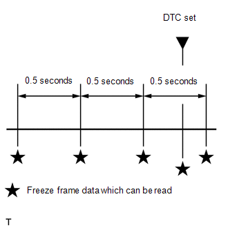
Status of IG Switch Terminal Low Voltage Guard Determination |
IGSW low voltage guard judgment |
When
other ECUs do not start while the ignition switch is off or the system
is unstable immediately after the ECM starts, DTCs cannot be accurately
detected. Therefore, the ignition switch is turned
off or 0.5 seconds after the ignition switch is turned to ON, this item
is set to "ON" to prohibit DTC detection. |
|
Status of Soak Timer Start |
Soak timer start condition |
- |
| Soak Timer Start Request |
Start signal from soak timer IC |
- |
| Soak IC Current Timer Value |
Current soak timer value |
P2610 clock comparison detection compares "Soak IC Current Timer Value" and "Soak Timer Clear" to detect malfunctions. |
|
Soak Timer Clear | Time elapsed since soak timer was cleared |
When the ignition switch is turned off after the engine starts, the "Soak Timer Clear" value is cleared. |
|
Soak Timer Start History |
Soak timer start history |
- |
| Soak IC First Start Time |
Initial soak timer start time |
First time soak timer started after ignition switch was turned off. |
|
Soak Start Count | Number of times soak timer started from ignition switch ON to ignition switch off |
- |
| Main Relay ON Time after IG OFF |
EFI relay ON time after ignition switch was turned off |
When the ignition switch is ON, this item displays 0 ms. |
|
Main Relay ON Time after IG OFF of Previous Trip |
EFI relay ON time after previous time ignition switch was turned off |
- |
| Main Relay ON Time after Soak Start of Previous Trip |
EFI relay ON time after previous clock comparison detection |
- |
| Power Steering Pressure |
Power steering oil pressure sensor |
- |
| ACT VSV |
A/C cut status for Active Test |
- |
| Electric Cooling Fan Low |
Electric fan motor operation status |
- |
| Brake Override System |
Brake Override System |
- |
| Idle Fuel Cut |
Fuel cut at idle | ON: when throttle valve fully closed and engine speed over 3500 rpm. |
|
FC TAU | Fuel cut during very light load |
Fuel cut being performed under very light load to prevent engine combustion from becoming incomplete. |
|
Immobiliser Fuel Cut | Status of the immobiliser fuel cut |
- |
| Immobiliser Fuel Cut History |
Status of the immobiliser fuel cut history |
- |
| Vehicle Spec Signal 1 |
Status of the Vehicle Spec Judge Signal 1 |
- |
| Electrical Load Signal 1 |
Electrical load signal 1 |
- |
| Electrical Load Signal 2 |
Electrical load signal 2 |
- |
| Cruise Main SW |
Status of the cruise main switch signal |
- |
| Cruise Cancel Signal |
Status of the cruise cancel signal |
- |
| A/F Sensor Determination (worst value) #1 |
Worst judgment value of air fuel ratio sensor output (bank 1) |
- |
| A/F Sensor Determination (worst value) #2 |
Worst judgment value of air fuel ratio sensor output (bank 2) |
- |
| Engine Speed Fluctuation Avg (worst value) #1 |
Worst value of average engine speed fluctuation (Cylinder No. 1) |
- |
| Engine Speed Fluctuation Avg (worst value) #2 |
Worst value of average engine speed fluctuation (Cylinder No. 2) |
- |
| Engine Speed Fluctuation Avg (worst value) #3 |
Worst value of average engine speed fluctuation (Cylinder No. 3) |
- |
| Engine Speed Fluctuation Avg (worst value) #4 |
Worst value of average engine speed fluctuation (Cylinder No. 4) |
- |
| Engine Speed Fluctuation Avg (worst value) #5 |
Worst value of average engine speed fluctuation (Cylinder No. 5) |
- |
| Engine Speed Fluctuation Avg (worst value) #6 |
Worst value of average engine speed fluctuation (Cylinder No. 6) |
- |
| Engine Speed Fluctuation Avg (worst value) #7 |
Worst value of average engine speed fluctuation (Cylinder No. 7) |
- |
| Engine Speed Fluctuation Avg (worst value) #8 |
Worst value of average engine speed fluctuation (Cylinder No. 8) |
- |
| SPD (NT) |
Input shaft speed | Data displayed in increments of 50 rpm. |
|
SPD (SP2) | Output shaft speed |
- |
| Shift SW Status (P Range) |
PNP switch status (P Range) | When
shift lever position displayed on Techstream differs from actual
position, adjustment of PNP switch or shift cable may be incorrect. |
|
Shift SW Status (R Range) | PNP switch status (R Range) |
When
shift lever position displayed on Techstream differs from actual
position, adjustment of PNP switch or shift cable may be incorrect. |
|
Shift SW Status (N Range) | Park/Neutral position (PNP) switch status (N Range) |
When
shift lever position displayed on Techstream differs from actual
position, adjustment of Park/Neutral position (PNP) switch signal or
shift cable may be incorrect. |
|
Shift SW Status (N,P Range) Supported |
Status of PNP switch (N or P) supported |
- |
| Shift SW Status (N,P Range) |
PNP switch status (N or P Range) |
- |
| Sports Shift Up SW |
Sport shift up switch status |
- |
| Sports Shift Down SW |
Sport shift down switch status |
- |
| Sports Mode Selection SW |
Sport mode select switch status |
- |
| Shift SW Status (D Range) |
PNP switch status (D Range) | When
shift lever position displayed on Techstream differs from actual
position, adjustment of PNP switch or shift cable may be incorrect. |
|
A/T Oil Temperature 1 | No. 1 ATF temperature sensor value |
If value -40°C (-40°F) or 215°C (419°F), No. 1 ATF temperature sensor circuit open or shorted. |
|
A/T Oil Temperature 2 | No. 2 ATF temperature sensor value |
If value -40°C (-40°F) or 215°C (419°F), No. 2 ATF temperature sensor circuit open or shorted. |
|
ATF Thermal Degradation Estimate |
Estimated value of ATF thermal degradation |
- |
| Lock Up |
Lock-up | - |
|
Shift Status | ECM gear shift command |
- |
| SLT Solenoid Status |
Shift solenoid SLT status |
- |
| SLU Solenoid Status |
Shift solenoid SLU status |
- |
| Torque Converter Temperature Raise History |
Torque converter temperature raise history status |
- |