DESCRIPTION The fuel pump circuit consists of the ECM, fuel pump and fuel pump ECU (which operates the fuel pump). Based on the engine output, the ECM determines the fuel pump speed. The speed is then converted to a duty signal and sent to the fuel pump ECU. Based on the signal sent from the ECM, the fuel pump ECU adjusts the fuel pump operation speed. WIRING DIAGRAM 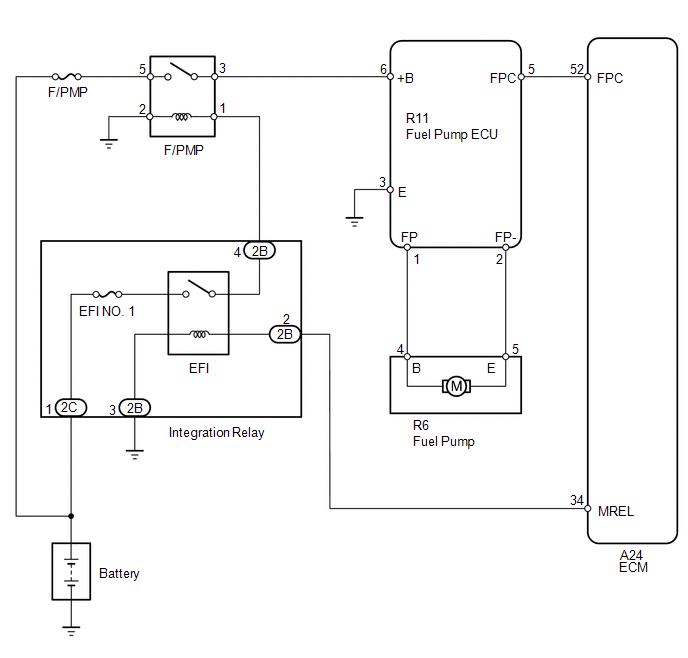 CAUTION / NOTICE / HINT NOTICE: Inspect the fuses for circuits related to this system before performing the following inspection procedure. PROCEDURE
(a) Connect the Techstream to the DLC3. (b) Turn the ignition switch to ON. (c) Turn the Techstream on. (d) Enter the following menus: Powertrain / Engine and ECT / Active Test / Control the Fuel Pump/Speed. (e) Check whether operating sounds can be heard while operating the fuel pump using the Techstream. OK: Operating sounds can be heard from fuel pump. Result
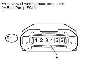
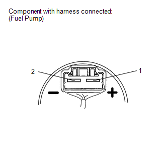
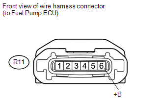 (a) Disconnect the fuel pump ECU connector. (b) Turn the ignition switch to ON. (c) Measure the voltage according to the value(s) in the table below. Standard Voltage:
 (a) Disconnect the fuel pump ECU connector. (b) Measure the resistance according to the value(s) in the table below. Standard Resistance:
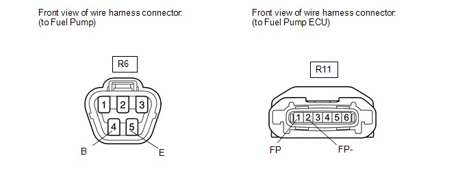 (a) Disconnect the fuel pump connector. (b) Disconnect the fuel pump ECU connector. (c) Measure the resistance according to the value(s) in the table below. Standard Resistance:
(a) Inspect the fuel pump (See page
HINT: Perform "Inspection After Repair" after replacing the fuel pump (See page
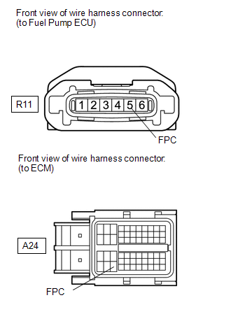 (a) Disconnect the fuel pump ECU connector. (b) Disconnect the ECM connector. (c) Measure the resistance according to the value(s) in the table below. Standard Resistance:
(a) Replace the fuel pump ECU (See page
(a) Check the fuel pump operation. OK: Malfunction has been repaired successfully.
(a) Inspect the fuel pump relay (F/PMP) (See page
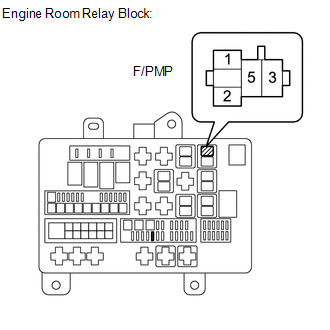 (a) Remove the fuel pump relay (F/PMP) from the engine room relay block. (b) Turn the ignition switch to ON. (c) Measure the voltage according to the value(s) in the table below. Standard Voltage:
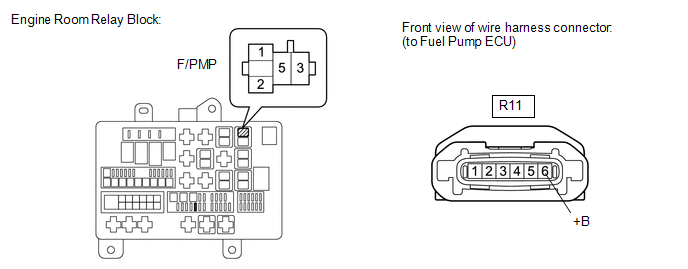 (a) Remove the fuel pump relay (F/PMP) from the engine room relay block. (b) Disconnect the fuel pump ECU connector. (c) Measure the resistance according to the value(s) in the table below. Standard Resistance:
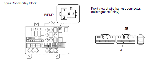 (a) Disconnect the cable from the battery negative (-) terminal. (b) Disconnect the cable from the battery positive (+) terminal. (c) Remove the fuel pump relay (F/PMP) from the engine room relay block. (d) Remove the integration relay from the engine room relay block. (e) Measure the resistance according to the value(s) in the table below. Standard Resistance:
 (a) Remove the fuel tank assembly (See page
(b) Remove the fuel pump from the fuel tank assembly. (c) Clean the fuel pump to completely remove any remaining fuel. (d) Connect the fuel pump connector. CAUTION: Confirm that no fuel remains inside or on the outside of the fuel pump. (e) Connect the Techstream to the DLC3. (f) Turn the ignition switch to ON. (g) Turn the Techstream on. (h) Enter the following menus: Powertrain / Engine and ECT / Active Test / Control the Fuel Pump Duty. (i) Operate the fuel pump using the active test function and measure the voltage according to the value(s) in the table below. Standard Voltage:
(j) Enter the following menus: Powertrain / Engine and ECT / Active Test / Control the Fuel Pump/Speed. (k) Operate the fuel pump using the active test function and measure the voltage according to the value(s) in the table below. Standard Voltage:
HINT:
(a) Disconnect the fuel pump ECU connector. (b) Disconnect the ECM connector. (c) Measure the resistance according to the value(s) in the table below. Standard Resistance:
(a) Replace the fuel pump (See page
HINT: Perform "Inspection After Repair" after replacing the fuel pump (See page
(a) Replace the fuel pump ECU (See page
(a) Check the fuel pump operation. OK: Malfunction has been repaired successfully.
|
Toyota Tundra Service Manual > Exterior: Fender Liner(for Rear Side)
Components COMPONENTS ILLUSTRATION Installation INSTALLATION CAUTION / NOTICE / HINT HINT: Use the same procedure for the RH and LH sides. The procedures listed below are for the LH side. PROCEDURE 1. INSTALL REAR WHEEL HOUSE LINER LH (a) Install the rear wheel house liner LH with 22 new grommets. ( ...


 ).
).
