DESCRIPTION
- Refer to DTC P0136 (See page
 ). ).
HINT:
- When any of these DTCs are stored, the ECM enters fail-safe mode. The
ECM turns off the Heated Oxygen (HO2) sensor heater in fail-safe mode.
Fail-safe mode continues until the ignition switch is turned off.
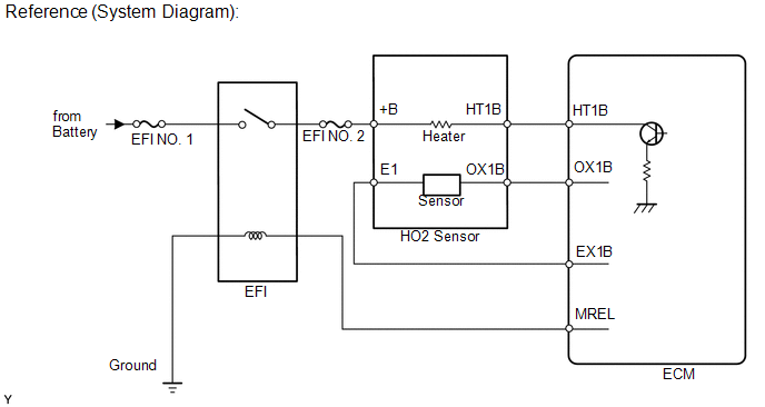
- The ECM provides a pulse width modulated control circuit to adjust the
current through the heater. The HO2 sensor heater circuit uses a relay
on the +B side of the circuit.
| DTC No. |
DTC Detection Condition | Trouble Area | |
P0037 P0057 | The heater current is less than the specified value while the heater is operating.
(1 trip detection logic) |
- Open in HO2 sensor heater circuit
- HO2 sensor heater (for Sensor 2)
- Integration relay
- ECM
| | P0038
P0058 | The heater current is higher than the specified value while the heater is operating.
(1 trip detection logic) |
- Short in HO2 sensor heater circuit
- HO2 sensor heater (for Sensor 2)
- Integration relay
- ECM
| | P0141
P0161 | The cumulative heater resistance correction value exceeds the threshold.
(2 trip detection logic) |
- Open or short in HO2 sensor heater circuit
- HO2 sensor heater (for Sensor 2)
- Integration relay
- ECM
| | P102D
P105D | The heater current is higher than the specified value while the heater is not operating.
(1 trip detection logic) | ECM | MONITOR DESCRIPTION
The
sensing portion of the Heated Oxygen (HO2) sensor has a zirconia
element which is used to detect the oxygen concentration in the exhaust
gas. If the zirconia element is at the appropriate temperature, and the
difference between the oxygen concentrations surrounding the inside and
outside surfaces of the sensor is large, the zirconia element generates
voltage signals. In order to increase the oxygen concentration detecting
capacity of the zirconia element, the ECM supplements the heat from the
exhaust with heat from a heating element inside the sensor. Heated oxygen sensor heater range check (P0037, P0038, P0057, P0058, P102D and P105D):
The ECM monitors the current applied to the HO2 sensor heater to check the heater for malfunctions.
If
the heater current is outside the normal range, the signal transmitted
by the HO2 sensor becomes inaccurate. When the current in the HO2 sensor
heater is outside the normal operating range, the ECM interprets this
as a malfunction in the sensor heater and stores a DTC. Heated oxygen sensor heater performance (P0141 and P0161):
After
the accumulated heater ON time exceeds 100 seconds, the ECM calculates
the heater resistance using the battery voltage and the current applied
to the heater. If the resistance is above the
threshold value, the ECM determines that there is a malfunction in the
HO2 sensor heater and stores DTC P0141 or P0161. MONITOR STRATEGY |
Related DTCs | P0037: Heated oxygen sensor heater (for Bank 1) range check (Low electrical current)
P0038: Heated oxygen sensor heater (for Bank 1) range check (High electrical current)
P0057: Heated oxygen sensor heater (for Bank 2) range check (Low electrical current)
P0058: Heated oxygen sensor heater (for Bank 2) range check (High electrical current)
P0141: Heated oxygen sensor heater performance (for Bank 1) P0161: Heated oxygen sensor heater performance (for Bank 2)
P102D: Heated oxygen sensor heater stuck ON (for Bank 1 Sensor 2) P105D: Heated oxygen sensor heater stuck ON (for Bank 2 Sensor 2) | |
Required Sensors/Components (Main) | Heated oxygen sensor heater | |
Required Sensors/Components (Related) | - | |
Frequency of Operation | Continuous: P0037, P0038, P0057, P0058 P102D and P105D
Once per driving cycle: P0141 and P0161 | |
Duration | 0.5 seconds: P0037 and P0057 Within 3 seconds: P0038 and P0058
10 seconds: P0141 and P0161 0.5 seconds: P102D and P105D | |
MIL Operation | Immediate: P0037, P0038, P0057, P0058, P102D and P105D
2 driving cycles: P0141 and P0161 | | Sequence of Operation |
None | TYPICAL ENABLING CONDITIONS P0037 and P0057 (Case 1) |
Monitor runs whenever following DTCs not stored |
P0038, P0058 (Rear oxygen sensor heater) | |
Battery voltage | 10.5 V or higher | |
Engine | Running | |
Starter | OFF | |
Catalyst active A/F control | Not operating | |
Time after heater ON | 10 seconds or more | |
Learned heater OFF current operation |
Complete | | Heater OFF current operation |
Succeeded | | Heater ON current - Learned heater OFF current |
0.3 A or less | | Heater output |
ON | P0037 and P0057 (Case 2) |
Monitor runs whenever following DTCs not stored |
P0038, P0058 (Rear oxygen sensor heater) | |
Battery voltage | 10.5 V or higher | |
Engine | Running | |
Starter | OFF | |
Catalyst active A/F control | Not operating | |
Time after heater ON | 10 seconds or more | |
Learned heater OFF current operation |
Complete | | Heated oxygen sensor heater OFF current |
Higher than 3.5 A | | Hybrid IC high current limiter port |
Fail | P0038 and P0058 |
Monitor runs whenever following DTCs not stored |
None | | Battery voltage |
10.5 V or higher | | Engine |
Running | | Starter |
OFF | | Catalyst active A/F control |
Not operating | | Time after heater ON |
10 seconds or more | | Learned heater OFF current operation |
Complete | P0141 and P0161 (Case 1) |
Monitor runs whenever following DTCs not stored |
P0037, P0038, P0057, P0058, P102D, P105D (Rear oxygen sensor heater) | |
Battery voltage | 10.5 V or higher | |
Fuel cut | OFF | |
Time after fuel cut ON to OFF | 30 seconds or more | |
Accumulated heater ON time | 100 seconds or more | |
Learned heater OFF current operation |
Complete | P0141 and P0161 (Case 2) |
Monitor runs whenever following DTCs not stored |
None | | Duration that rear heated oxygen sensor impedance is less than 15 kΩ |
2 seconds or more | P102D and P105D |
Monitor runs whenever following DTCs not stored |
P0037, P0038, P0057, P0058 (Rear oxygen sensor heater) | |
Battery voltage | 10.5 V or higher | |
Engine | Running | |
Starter | OFF | |
Catalyst active A/F control | Not operating | |
Time after heater ON | 10 seconds or more | |
Learned heater OFF current operation |
Complete | | Hybrid IC high current limiter port |
Fail | TYPICAL MALFUNCTION THRESHOLDS P0037 and P0057 (Case 1) |
Heater current - Learned heater OFF current |
0.3 A or less | P0037 and P0057 (Case 2) |
Heated oxygen sensor heater ON current | 1 A or less | P0038 and P0058 |
Hybrid IC high current limiter port | Fail | |
Heated oxygen sensor heater output | ON | P0141 and P0161 |
Accumulated heater resistance | Varies with sensor element temperature (Example: Higher than 23 Ω) | P102D and P105D |
Heated oxygen sensor heater ON current | Higher than 1 A | COMPONENT OPERATING RANGE |
Heated Oxygen (HO2) sensor heater current | 0.4 to 1 A (when engine idles, HO2 sensor warmed up and battery voltage 11 to 14 V) | MONITOR RESULT
Refer to Checking Monitor Status (See page ). CONFIRMATION DRIVING PATTERN
- Connect the Techstream to the DLC3.
- Turn the ignition switch to ON and turn the Techstream ON.
- Clear DTCs (even if no DTCs are stored, perform the clear DTC operation).
- Turn the ignition switch off and wait for at least 30 seconds.
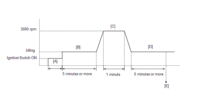
- Turn the ignition switch to ON and turn the Techstream on [A].
- Start the engine and idle it for 5 minutes or more [B].
- With the vehicle stationary, depress the accelerator pedal and maintain an engine speed of 3000 rpm for 1 minute [C].
- Idle the engine for 5 minutes or more [D].
- Enter the following menus: Powertrain / Engine and ECT / Trouble Codes [E].
- Read the pending DTCs.
HINT:
- If a pending DTC is output, the system is malfunctioning.
- If a pending DTC is not output, perform the following procedure.
- Enter the following menus: Powertrain / Engine and ECT / Utility / All Readiness.
- Input the DTC: P0037, P0038, P0057, P0058, P0141, P0161, P102D or P105D.
- Check the DTC judgment result.
|
Tester Display |
Description |
|
NORMAL |
- DTC judgment completed
- System normal
|
|
ABNORMAL |
- DTC judgment completed
- System abnormal
|
|
INCOMPLETE |
- DTC judgment not completed
- Perform driving pattern after confirming DTC enabling conditions
|
|
N/A |
- Unable to perform DTC judgment
- Number of DTCs which do not fulfill DTC preconditions has reached ECU memory limit
|
- If the judgment result shows INCOMPLETE or N/A, perform steps [B] through [E] again.
- If no pending DTC is output, perform a universal trip and check for permanent DTCs (See page
).
HINT:
- If a permanent DTC is output, the system is malfunctioning.
- If no permanent DTC is output, the system is normal.
WIRING DIAGRAM Refer to DTC P0136 (See page
). CAUTION / NOTICE / HINT
HINT:
PROCEDURE |
1. | INSPECT HEATED OXYGEN SENSOR (HEATER RESISTANCE) |
(a) Inspect the heated oxygen sensor (See page
). HINT: Perform "Inspection After Repair" after replacing the heated oxygen sensor (See page
).
| NG |  |
REPLACE HEATED OXYGEN SENSOR |
|
OK |
 | |
| 2. |
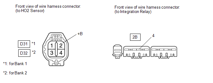
CHECK TERMINAL VOLTAGE (+B OF HO2 SENSOR) |
 (a) Disconnect the HO2 sensor connector.
(b) Turn the ignition switch to ON. (c) Measure the voltage according to the value(s) in the table below.
Standard Voltage: |
Tester Connection | Switch Condition |
Specified Condition | |
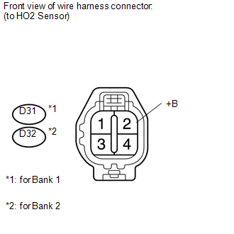
D31-2 (+B) - Body ground |
Ignition switch ON | 11 to 14 V | |
D32-2 (+B) - Body ground |
Ignition switch ON | 11 to 14 V | Result |
Result | Proceed to | |
NG | A | |
OK | B |
| B |
| GO TO STEP 5 |
|
A | |
| |
| 3. |
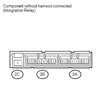
INSPECT INTEGRATION RELAY (EFI) | (a) Remove the integration relay from the engine room relay block.
(b) Inspect the EFI NO. 1 fuse. (1) Remove the EFI NO. 1 fuse from the integration relay.
(2) Measure the resistance according to the value(s) in the table below.
Standard Resistance: |
Tester Connection | Condition |
Specified Condition | |
EFI NO. 1 fuse | Always |
Below 1 Ω | (3) Reinstall the EFI NO. 1 fuse.
 (c) Inspect the EFI relay.
(1) Measure the resistance according to the value(s) in the table below.
Standard Resistance: |
Tester Connection | Condition |
Specified Condition | |
2C-1 - 2B-4 | No battery voltage applied to terminals 2B-2 and 2B-3 |
10 kΩ or higher | |
Battery voltage applied to terminals 2B-2 and 2B-3 |
Below 1 Ω |
| NG |
| REPLACE INTEGRATION RELAY (EFI) |
|
OK | |
| |
| 4. |
CHECK HARNESS AND CONNECTOR (HO2 SENSOR - INTEGRATION RELAY) |
(a) Check the EFI NO. 2 fuse. (1) Remove the EFI NO. 2 fuse from the engine room relay block.
(2) Measure the resistance according to the value(s) in the table below.
Standard Resistance: |
Tester Connection | Condition |
Specified Condition | |
EFI NO. 2 fuse | Always |
Below 1 Ω | (3) Reinstall the EFI NO. 2 fuse.
 (b) Disconnect the HO2 sensor connector.
(c) Remove the integration relay from the engine room relay block. (d) Measure the resistance according to the value(s) in the table below.
Standard Resistance: |
Tester Connection | Condition |
Specified Condition | |
D31-2 (+B) - 2B-4 | Always |
Below 1 Ω | |
D32-2 (+B) - 2B-4 | Always |
Below 1 Ω | |
D31-2 (+B) or 2B-4 - Body ground |
Always | 10 kΩ or higher | |
D32-2 (+B) or 2B-4 - Body ground |
Always | 10 kΩ or higher |
| OK |
| CHECK ECM POWER SOURCE CIRCUIT |
| NG |
| REPAIR OR REPLACE HARNESS OR CONNECTOR |
| 5. |
CHECK HARNESS AND CONNECTOR (HO2 SENSOR - ECM) |
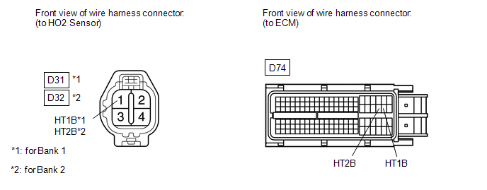 (a) Disconnect the HO2 sensor connector.
(b) Disconnect the ECM connector. (c) Measure the resistance according to the value(s) in the table below.
Standard Resistance: |
Tester Connection | Condition |
Specified Condition | |
D31-1 (HT1B) - D74-45 (HT1B) |
Always | Below 1 Ω | |
D32-1 (HT2B) - D74-44 (HT2B) |
Always | Below 1 Ω | |
D31-1 (HT1B) or D74-45 (HT1B) - Body ground |
Always | 10 kΩ or higher | |
D32-1 (HT2B) or D74-44 (HT2B) - Body ground |
Always | 10 kΩ or higher |
| NG |
| REPAIR OR REPLACE HARNESS OR CONNECTOR |
|
OK | |
| |
| 6. |
CHECK WHETHER DTC OUTPUT RECURS | (a) Connect the Techstream to the DLC3.
(b) Turn the ignition switch to ON. (c) Turn the Techstream on.
(d) Clear DTCs (See page ). (e) Start the engine.
(f) Drive the vehicle in accordance with the driving pattern described in the Confirmation Driving Pattern.
(g) Read the output pending DTCs using the Techstream. Result |
Result | Proceed to | |
No pending DTC is output |
A | | Pending DTC P0037, P0038, P0057, P0058, P0141, P0161, P102D and/or P105D is output |
B |
| A |
| CHECK FOR INTERMITTENT PROBLEMS |
| B |
| REPLACE ECM | |


