DESCRIPTION Refer to DTC P0115 (See page
 ). ). |
DTC No. | DTC Detection Condition |
Trouble Area | | P0116 |
When either of following conditions met (2 trip detection logic):
- When cold engine started and engine warmed up, Engine Coolant Temperature (ECT) sensor value does not change.
- After warmed up engine stopped and then next cold engine start performed, ECT sensor value does not change.
|
- Water inlet with thermostat sub-assembly
- ECT sensor
| MONITOR DESCRIPTION Engine Coolant Temperature (ECT) sensor cold start monitor
When
a cold engine start is performed and then the engine is warmed up, if
the ECT sensor value does not change, it is determined that a
malfunction has occurred. If this is detected in 2 consecutive driving
cycles, the MIL is illuminated and a DTC is stored. ECT sensor soak monitor
If
the ECT sensor value does not change after the warmed up engine is
stopped and then the next cold engine start is performed, it is
determined that a malfunction has occurred. If this is detected in 2
consecutive driving cycles, the MIL is illuminated and a DTC is stored. MONITOR STRATEGY |
Related DTCs | P0116: Engine Coolant Temperature (ECT) sensor cold start monitor
P0116: ECT sensor soak monitor | | Required Sensors/Components (Main) |
ECT sensor | | Required Sensors/Components (Related) |
None | | Frequency of Operation |
Once per driving cycle | | Duration |
-: Cold start monitor 10 seconds: Soak monitor | |
MIL Operation | 2 driving cycles | |
Sequence of Operation | None | TYPICAL ENABLING CONDITIONS ECT Sensor Cold Start Monitor |
Monitor runs whenever following DTCs not present |
P0112, P0113 (Intake air temperature sensor) P0115, P0117, P0118 (Engine coolant temperature sensor)
P0125 (Insufficient coolant temperature for closed loop fuel control)
P0128 (Thermostat) | | Battery voltage |
10.5 V or more | | Time after engine start |
1 second or more | | ECT at engine start |
Less than 60°C (140°F) | | Soak time |
0 seconds or more | | Accumulated MAF |
5228 g or more | | Fuel cut |
OFF | | Difference between ECT at engine start and IAT |
Less than 40°C (104°F) | ECT Sensor Soak Monitor |
Monitor runs whenever following DTCs not present |
P0112, P0113 (Intake air temperature sensor) P0115, P0117, P0118 (Engine coolant temperature sensor)
P0125 (Insufficient coolant temperature for closed loop fuel control)
P0128 (Thermostat) P2610 (Soak timer) | |
Battery voltage | 10.5 V or more | |
Engine | Running | |
Soak time | 5 hours or more | |
Either condition (a) or (b) met | - | |
(a) ECT | 60°C (140°F) or more | |
(b) Accumulated MAF | 10456 g or more | TYPICAL MALFUNCTION THRESHOLDS ECT Sensor Cold Start Monitor |
ECT sensor value change | Less than 5°C (41°F) | ECT Sensor Soak Monitor |
Difference between current ECT sensor value and previous ECT sensor value when engine stopped |
Less than 5°C (41°F) [varies with ECT of last trip engine stop] | COMPONENT OPERATING RANGE |
ECT | ECT sensor value changes in accordance with actual ECT | CONFIRMATION DRIVING PATTERN
- Connect the Techstream to the DLC3.
- Turn the ignition switch to ON and turn the Techstream on.
- Enter the following menu items: Powertrain / Engine and ECT / Data List / Coolant Temp.
- Check that the coolant temperature is 60°C (140°F) or less.
- Clear DTCs (even if no DTCs are stored, perform the clear DTC operation).
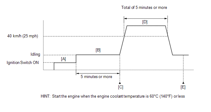
- Turn the ignition switch off and wait for at least 30 seconds.
- Turn the ignition switch to ON and turn the Techstream on [A].
- Start the engine and idle it for 5 minutes or more [B].
HINT:
If
the engine coolant temperature does not change by 5°C (9°F) or higher,
the ECT sensor is malfunctioning. It is not necessary to continue this
procedure.
- Enter the following menus: Powertrain / Engine and ECT / Trouble Codes [C].
- Read the pending DTCs.
HINT:
- If a pending DTC is output, the system is malfunctioning.
- If a pending DTC is not output, perform the following procedure.
- Enter the following menus: Powertrain / Engine and ECT / Utility / All Readiness.
- Input the DTC: P0116.
- Check the DTC judgment result.
|
Tester Display |
Description |
|
NORMAL |
- DTC judgment completed
- System normal
|
|
ABNORMAL |
- DTC judgment completed
- System abnormal
|
|
INCOMPLETE |
- DTC judgment not completed
- Perform driving pattern after confirming DTC enabling conditions
|
|
N/A |
- Unable to perform DTC judgment
- Number of DTCs which do not fulfill DTC preconditions has reached ECU memory limit
|
HINT:
If the judgment result shows INCOMPLETE or N/A, perform steps [D] and [E].
- Drive the vehicle at 40 km/h (25 mph) or more for a total of 5 minutes or more [D].
CAUTION:
When performing the confirmation driving pattern, obey all speed limits and traffic laws.
HINT:
In
the event of the drive pattern being interrupted (possibly due to
factors such as traffic conditions), the drive pattern can be resumed.
- Check the DTC judgment result again [E].
HINT:
If the judgment result shows INCOMPLETE or N/A, perform steps [D] and [E] again.
- If no pending DTC is output, perform a universal trip and check for permanent DTCs (See page
).
HINT:
- If a permanent DTC is output, the system is malfunctioning.
- If no permanent DTC is output, the system is normal.
CAUTION / NOTICE / HINT
HINT:
- If DTC P0115, P0117, P0118 or P0125 is stored simultaneously with DTC
P0116, the ECT sensor may have an open or short circuit. Troubleshoot
those DTCs first.
- Read freeze frame data using the Techstream. Freeze frame data records
the engine condition when malfunctions are detected. When
troubleshooting, freeze frame data can help determine if the vehicle was
moving or stationary, if the engine was warmed up or not, if the
air-fuel ratio was lean or rich, and other data from the time the
malfunction occurred.
PROCEDURE |
1. | CHECK ANY OTHER DTCS OUTPUT (IN ADDITION TO DTC P0116) |
(a) Connect the Techstream to the DLC3. (b) Turn the ignition switch to ON.
(c) Turn the Techstream on. (d) Enter the following menus: Powertrain / Engine and ECT / Trouble Codes.
(e) Read the DTCs. Result |
Result | Proceed to | |
P0116 is output | A | |
P0116 and other DTCs are output |
B | HINT: If any DTCs other than P0116 are output, perform troubleshooting for those DTCs first.
| B |
 | GO TO DTC CHART |
|
A |  | |
| 2. |
INSPECT WATER INLET WITH THERMOSTAT SUB-ASSEMBLY |
(a) Remove the water inlet with thermostat sub-assembly (See page
). (b) Measure the valve opening temperature of the water inlet with thermostat sub-assembly.
Standard opening temperature: 80 to 84°C (176 to 183°F)
HINT:
- In addition to the above check, confirm that the valve is completely closed when the temperature is below the standard.
- Perform "Inspection After Repair" after replacing the engine coolant temperature sensor (See page
).
| OK |
| REPLACE ENGINE COOLANT TEMPERATURE SENSOR |
| NG |
| REPLACE WATER INLET WITH THERMOSTAT SUB-ASSEMBLY | |


