Toyota Tundra Service Manual: System Voltage (P0560)

DESCRIPTION

The battery supplies electricity to the ECM even when the ignition switch is off. This power allows the ECM to store data such as DTC history, freeze frame data and fuel trim values. If the battery voltage falls below a minimum level, the memory is cleared and the ECM determines that there is a malfunction in the power supply circuit. When the engine is next started, the ECM illuminates the MIL and stores the DTC.

DTC No.

DTC Detection Condition

Trouble Area

P0560

Open in ECM back up power source circuit

(1 trip detection logic)

  • Open in back up power source circuit
  • Battery
  • Battery terminals
  • EFI NO. 1 fuse
  • ECM

HINT:

If DTC P0560 is stored, the ECM does not store other DTCs or the data stored in the ECM is partly cleared.

MONITOR STRATEGY

Related DTCs

P0560: ECM system voltage

Required Sensors/Components (Main)

ECM

Required Sensors/Components (Related)

-

Frequency of Operation

Continuous

Duration

3 seconds

MIL Operation

Immediate (MIL illuminated after next engine start)

Sequence of Operation

None

TYPICAL ENABLING CONDITIONS

Monitor runs whenever following DTCs not present

None

TYPICAL MALFUNCTION THRESHOLDS

Stand-by RAM

Initialized

ECM power source

Less than 3.5 V

CONFIRMATION DRIVING PATTERN

  1. Connect the Techstream to the DLC3.
  2. Turn the ignition switch to ON and turn the Techstream on.
  3. Clear DTCs (even if no DTCs are stored, perform the clear DTC operation).
  4. Turn the ignition switch off and wait for at least 30 seconds.
  5. Turn the ignition switch to ON and turn the Techstream on.
  6. Wait 5 seconds or more.
  7. Enter the following menus: Powertrain / Engine and ECT / Trouble Codes.
  8. Read the pending DTCs.

    HINT:

    • If a pending DTC is output, the system is malfunctioning.
    • If a pending DTC is not output, perform the following procedure.
  9. Enter the following menus: Powertrain / Engine and ECT / Utility / All Readiness.
  10. Input the DTC: P0560.
  11. Check the DTC judgment result.

    Tester Display

    Description

    NORMAL

    • DTC judgment completed
    • System normal

    ABNORMAL

    • DTC judgment completed
    • System abnormal

    INCOMPLETE

    • DTC judgment not completed
    • Perform driving pattern after confirming DTC enabling conditions

    N/A

    • Unable to perform DTC judgment
    • Number of DTCs which do not fulfill DTC preconditions has reached ECU memory limit

    HINT:

    If the judgment result shows ABNORMAL, the system has a malfunction.

  12. If the test result is INCOMPLETE or N/A and no pending DTC is output, perform a universal trip and check for permanent DTCs (See page ).

    HINT:

    • If a permanent DTC is output, the system is malfunctioning.
    • If no permanent DTC is output, the system is normal.

WIRING DIAGRAM

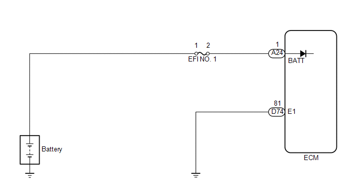
CAUTION / NOTICE / HINT

NOTICE:

After turning ignition switch off, waiting time may be required before disconnecting the cable from the negative (-) battery terminal. Therefore, make sure to read the disconnecting the cable from the negative (-) battery terminal notices before proceeding with work (See page ).

HINT:

Read freeze frame data using the Techstream. Freeze frame data records the engine condition when malfunctions are detected. When troubleshooting, freeze frame data can help determine if the vehicle was moving or stationary, if the engine was warmed up or not, if the air-fuel ratio was lean or rich, and other data from the time the malfunction occurred.

PROCEDURE

1.

INSPECT FUSE (EFI NO. 1)

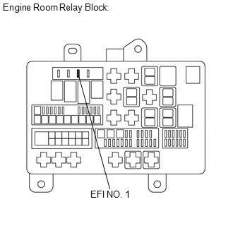
(a) Remove the EFI NO. 1 fuse from the engine room relay block.

(b) Measure the resistance according to the value(s) in the table below.

Standard Resistance:

Tester Connection

Condition

Specified Condition

EFI NO. 1 fuse

Always

Below 1 Ω

NG

CHECK FOR SHORTS IN ALL HARNESSES AND CONNECTORS CONNECTED TO FUSE AND REPLACE FUSE

OK

2.

CHECK HARNESS AND CONNECTOR (EFI NO. 1 FUSE - ECM, BATTERY)

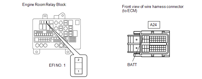
(a) Check the harness and connector between the EFI NO. 1 fuse and ECM.

(1) Remove the EFI NO. 1 fuse from the engine room relay block.

(2) Disconnect the ECM connector.

(3) Measure the resistance according to the value(s) in the table below.

Standard Resistance:

Tester Connection

Condition

Specified Condition

EFI NO. 1 fuse terminal 2 - A24-1 (BATT)

Always

Below 1 Ω

EFI NO. 1 fuse terminal 2 or A24-1 (BATT) - Body ground

Always

10 kΩ or higher

(b) Check the harness and connector between the EFI NO. 1 fuse and battery.

(1) Remove the EFI NO. 1 fuse from the engine room relay block.

(2) Disconnect the negative battery terminal.

(3) Disconnect the positive battery terminal.

(4) Measure the resistance according to the value(s) in the table below.

Standard Resistance:

Tester Connection

Condition

Specified Condition

Battery positive (+) terminal - EFI NO. 1 fuse terminal 1

Always

Below 1 Ω

Battery positive (+) terminal or EFI NO. 1 fuse terminal 1- Body ground

Always

10 kΩ or higher

NG

REPAIR OR REPLACE HARNESS OR CONNECTOR

OK

3.

INSPECT BATTERY

(a) Check that the battery is not depleted (See page ).

OK:

Battery is not depleted.

NG

REPLACE BATTERY

OK

4.

CHECK BATTERY TERMINAL

(a) Check that the battery terminals are not loose or corroded.

OK:

Battery terminals are not loose or corroded.

NG

REPAIR BATTERY TERMINAL

OK

5.

CHECK WHETHER DTC OUTPUT RECURS

(a) Connect the Techstream to the DLC3.

(b) Turn the ignition switch to ON.

(c) Turn the Techstream on.

(d) Clear DTCs (See page ).

(e) Turn the ignition switch off.

(f) Turn the ignition switch to ON and turn the Techstream on.

(g) Wait 5 seconds or more.

(h) Enter the following menus: Powertrain / Engine and ECT / Trouble Codes.

(i) Read DTCs.

Result

Result

Proceed to

P0560 is output

A

No DTC is output

B

A

REPLACE ECM

B

CHECK FOR INTERMITTENT PROBLEMS

    Power Steering Pressure Sensor Circuit (P0550,P0552,P0553)

    Random Access Memory (RAM) (P0604)

    See More:

    Toyota Tundra Service Manual > Meter / Gauge System: Parts Location
    PARTS LOCATION ILLUSTRATION *A w/ Blind Spot Monitor System - - *1 HEADLIGHT ASSEMBLY LH - FRONT TURN SIGNAL LIGHT BULB SOCKET LH *2 HEADLIGHT ASSEMBLY RH - FRONT TURN SIGNAL LIGHT BULB SOCKET RH *3 REAR COMBINATION LIGHT ASSEMBLY LH - REAR TURN SIGNAL LIGHT BULB SOCKET LH *4 REAR COMBINATION LIGHT ...

    Toyota Tundra Owners Manual

    Toyota Tundra Service Manual

    © 2024 Copyright www.ttundra.com
    0.0109