DESCRIPTION The camshaft position sensor (G signal) consists of a magnet and MRE (Magnetoresistive Element).
The
camshaft drive gear (LH) has 3 teeth on its outer circumference. When
the camshaft gear rotates, the air gap between the protrusion on the
gear and the MRE changes. The change affects the magnetic field and
results in changes in the resistance of the MRE. The
crankshaft sensor plate has 34 teeth and is mounted on the crankshaft.
The crankshaft position sensor generates 34 signals per crankshaft
revolution. The ECM detects the standard crankshaft angle based on the G
signal, and the actual crankshaft angle and engine speed by the NE
signal. | DTC No. |
DTC Detection Condition | Trouble Area | |
P1340 | No camshaft position sensor signal to ECM during cranking (2 trip detection logic) |
- Open or short in camshaft position sensor circuit
- Camshaft position sensor
- Camshaft timing plate LH
- ECM
| | No camshaft position sensor signal to ECM with engine speed 600 rpm or more (1 trip detection logic) | |
P1342 | Output voltage of camshaft position sensor less than 0.3 V for 4 seconds
(1 trip detection logic) | |
P1343 | Output voltage of camshaft position sensor more than 4.7 V for 4 seconds
(1 trip detection logic) | MONITOR DESCRIPTION
If
no signal is transmitted by the camshaft position sensor despite the
engine running, or the rotations of the camshaft and crankshaft are not
synchronized, the ECM interprets this as a malfunction of the sensor.
Also, when the sensor output voltage remains below 0.3 V, or higher than
4.7 V for more than 4 seconds, the ECM stores a DTC. MONITOR STRATEGY |
Related DTCs | P1340: Camshaft position sensor verify pulse input
P1340: Camshaft position / Crankshaft position misalignment P1342: Camshaft position sensor range check (low voltage)
P1343: Camshaft position sensor range check (high voltage) | |
Required Sensors/Components (Main) | Camshaft position sensor | |
Required Sensors/Components (Related) |
Crankshaft position sensor, Engine speed sensor | |
Frequency of Operation | Continuous | |
Duration | 4 seconds: P1340 camshaft position sensor verify pulse input
P1342: Camshaft position sensor range check (low voltage) P1343: Camshaft position sensor range check (high voltage)
5 seconds: P1340 camshaft position / crankshaft position misalignment | |
MIL Operation | 2 driving cycles: P1340 camshaft position sensor verify pulse input
Immediate: P1340 camshaft position / crankshaft position misalignment and P1342, P1343 camshaft position sensor range check | |
Sequence of Operation | None | TYPICAL ENABLING CONDITIONS P1340 Camshaft Position Sensor Verify Pulse Input |
Monitor runs whenever following DTCs not present |
None | | Starter |
ON (Not including when starter turned ON multiple times) | |
Minimum battery voltage while starter ON |
Less than 11 V | P1340 Camshaft Position / Crankshaft Position Misalignment |
Monitor runs whenever following DTCs not present |
P0342, P0343 (VVT sensor) P1342, P1343 (Camshaft position sensor) | |
Engine RPM | 600 rpm or more | |
Starter | OFF | |
Camshaft position sensor range | 0.3 to 4.7 V | P1342, P1343 Camshaft Position Sensor Range Check |
Monitor runs whenever following DTCs not present |
P0340 (VVT sensor) P1340 (Camshaft position sensor) | |
Time after ignition switch off to ON | 2 seconds or more | |
Battery voltage | 8 V or more | |
Starter | OFF | TYPICAL MALFUNCTION THRESHOLDS P1340 Camshaft Position Sensor Verify Pulse Input |
Camshaft position signal | No signal | P1340 Camshaft Position / Crankshaft Position Misalignment |
Camshaft position and crankshaft position phase |
Misaligned | P1342 Camshaft Position Sensor Range Check |
Camshaft position sensor voltage | Less than 0.3 V | P1343 Camshaft Position Sensor Range Check |
Camshaft position sensor voltage | More than 4.7 V | COMPONENT OPERATING RANGE |
Camshaft position sensor signal |
- Camshaft position sensor voltage fluctuates when the camshaft rotates
- 3 signals per revolution of camshaft
| CONFIRMATION DRIVING PATTERN
- Connect the Techstream to the DLC3.
- Turn the ignition switch to ON and turn the Techstream on.
- Clear DTCs (even if no DTCs are stored, perform the clear DTC operation).
- Turn the ignition switch off and wait for at least 30 seconds.
- Turn the ignition switch to ON and turn the Techstream on [A].
- Start the engine.
- Idle the engine for 10 seconds or more.
- Enter the following menus: Powertrain / Engine and ECT / Trouble Codes [B].
- Read the pending DTCs.
HINT:
- If a pending DTC is output, the system is malfunctioning.
- If a pending DTC is not output, perform the following procedure.
- Enter the following menus: Powertrain / Engine and ECT / Utility / All Readiness.
- Input the DTC: P1340, P1342 or P1343.
- Check the DTC judgment result.
|
Tester Display |
Description |
|
NORMAL |
- DTC judgment completed
- System normal
|
|
ABNORMAL |
- DTC judgment completed
- System abnormal
|
|
INCOMPLETE |
- DTC judgment not completed
- Perform driving pattern after confirming DTC enabling conditions
|
|
N/A |
- Unable to perform DTC judgment
- Number of DTCs which do not fulfill DTC preconditions has reached ECU memory limit
|
HINT:
If the judgment result shows INCOMPLETE or N/A, perform steps [A] through [B] again.
- If no pending DTC is output, perform a universal trip and check for permanent DTCs (See page
 ). ).
HINT:
- If a permanent DTC is output, the system is malfunctioning.
- If no permanent DTC is output, the system is normal.
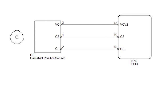
WIRING DIAGRAM
 CAUTION / NOTICE / HINT
HINT: Read
freeze frame data using the Techstream. Freeze frame data records the
engine conditions when malfunctions are detected. When troubleshooting,
freeze frame data can help determine if the vehicle was moving or
stationary, if the engine was warmed up or not, if the air fuel ratio
was lean or rich, and other data from the time the malfunction occurred. PROCEDURE
| 1. |
INSPECT CAMSHAFT POSITION SENSOR (SENSOR POWER SOURCE) |
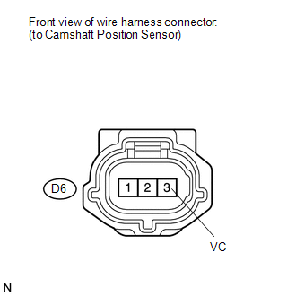 (a) Disconnect the camshaft position sensor connector.
(b) Turn the ignition switch to ON. (c) Measure the voltage according to the value(s) in the table below.
Standard Voltage: |
Tester Connection | Switch Condition |
Specified Condition | |
D6-3 (VC) - Body ground |
Ignition switch ON | 4.5 to 5.0 V |
| NG |
 | REPAIR OR REPLACE HARNESS OR CONNECTOR |
|
OK |
 | |
| 2. |
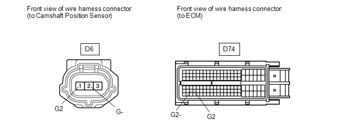
CHECK HARNESS AND CONNECTOR (ECM - CAMSHAFT POSITION SENSOR) |
 (a) Disconnect the camshaft position sensor connector.
(b) Disconnect the ECM connector. (c) Measure the resistance according to the value(s) in the table below.
Standard Resistance: |
Tester Connection | Condition |
Specified Condition | |
D6-1 (G2) - D74-90 (G2) |
Always | Below 1 Ω | |
D6-2 (G-) - D74-89 (G2-) |
Always | Below 1 Ω | |
D6-1 (G2) or D74-90 (G2) - Body ground |
Always | 10 kΩ or higher | |
D6-2 (G-) or D74-89 (G2-) - Body ground |
Always | 10 kΩ or higher |
| NG |
| REPAIR OR REPLACE HARNESS OR CONNECTOR |
|
OK | |
| |
| 3. |
CHECK SENSOR INSTALLATION |
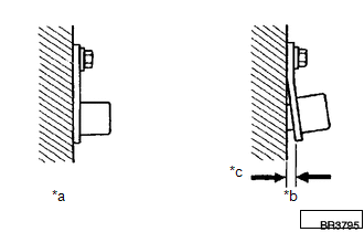 (a) Check the camshaft position sensor installation.
OK: The camshaft position sensor is installed properly.
| NG |
| SECURELY REINSTALL SENSOR |
|
OK | |
| |
| 4. |
INSPECT CAMSHAFT TIMING PLATE (SENSOR PLATE TOOTH) |
(a) Check the teeth of the sensor plate. OK: Sensor plate teeth do not have any cracks or deformation.
| NG |
| REPLACE CAMSHAFT TIMING PLATE |
|
OK | |
| |
| 5. |
REPLACE CAMSHAFT POSITION SENSOR | (a) Replace the camshaft position sensor (See page
).
|
NEXT | |
| |
| 6. |
CHECK WHETHER DTC OUTPUT RECURS | (a) Connect the Techstream to the DLC3.
(b) Turn the ignition switch to ON. (c) Turn the Techstream on.
(d) Clear DTCs (See page ). (e) Drive the vehicle in accordance with the driving pattern described in the Confirmation Driving Pattern.
(f) Read DTCs. Result |
Result | Proceed to | |
No DTC is output | A | |
P1340, P1342 and/or P1343 is output |
B | HINT: If the engine does not start, replace the ECM.
| A |
| END |
| B |
| REPLACE ECM | | 

