REASSEMBLY CAUTION / NOTICE / HINT
HINT: Perform "Inspection After Repairs" after replacing the piston or piston ring (See page
 ). ). PROCEDURE 1. INSTALL STUD BOLT
(a) Using an E8 "TORX" socket wrench, install the stud bolts.
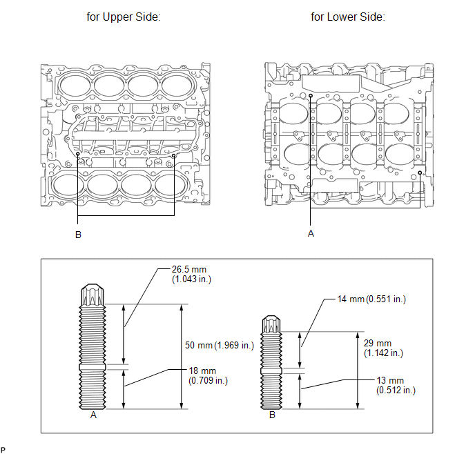 Torque: for stud bolt A :
20 N·m {204 kgf·cm, 15 ft·lbf} for stud bolt B : 9.0 N·m {92 kgf·cm, 80 in·lbf}
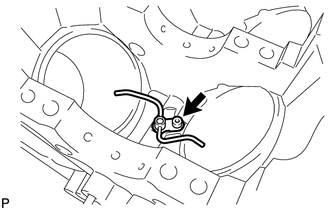
2. INSTALL NO. 1 OIL NOZZLE SUB-ASSEMBLY
| (a) Using a 5 mm hexagon wrench, install the 4 oil nozzles with the 4 bolts.
Torque: 10 N·m {102 kgf·cm, 7 ft·lbf} | |
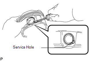
3. INSTALL PISTON WITH PIN SUB-ASSEMBLY HINT: Perform "Inspection After Repairs" after replacing the piston sub-assembly (See page
).
| (a) Using a small screwdriver, install a new snap ring at one end of the piston pin hole.
HINT: Be sure that the end gap of the snap ring is not aligned with the service hole of the piston. |
|
| (b) Gradually heat the piston to approximately 80°C (176°F). |
|
(c) Coat the piston pin and connecting rod with engine oil.
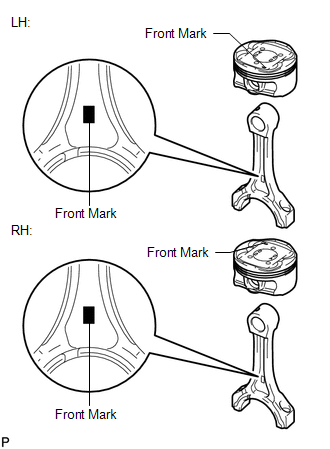
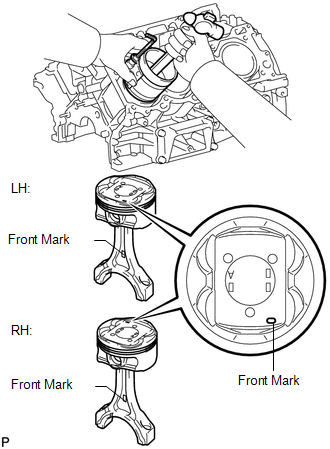
| (d)
Align the front marks of the piston and connecting rod as shown in the
illustration. Then push in the piston pin with your thumb until the
piston pin contacts the snap ring. NOTICE: For
the LH side, perform the assembly so that the front marks of the piston
and connecting rod are on the same side. For the RH side, perform the
assembly so that the front marks of the piston and connecting rod are on
opposite sides. HINT: The piston and pin are a matched set. |
|
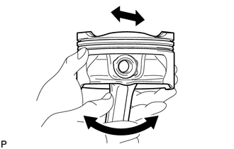
(e) Check the fitting condition between the piston and piston pin.
| (1) Move the connecting rod back and forth on the piston pin. Check the fitting condition.
If abnormal movement is felt, replace the piston and pin as a set. |
|
(2) Rotate the piston back and forth on the piston pin. Check the fitting condition.
If abnormal movement is felt, replace the piston and pin as a set.
| (f) Using a small screwdriver, install a new snap ring at the other end of the piston pin hole.
HINT: Be sure that the end gap of the snap ring is not aligned with the pin hole cutout portion of the piston. |
|
4. INSTALL PISTON RING SET HINT: Perform " Inspection After Repairs" after replacing the piston ring (See page
).
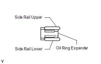
| (a) Install the oil ring expander and 2 side rails by hand. |
|
(b)
Using a piston ring expander, install the 2 compression rings so that
the paint marks are positioned as shown in the illustration.
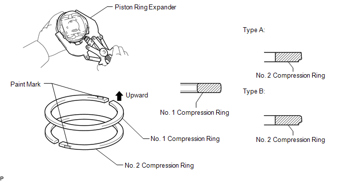 HINT: Type A and type B can be distinguished by the color of the paint marks or the cross-section shape of the No. 2 compression ring. |
Item | Paint Mark | |
Type A | No. 1 Compression Ring |
Blue | | No. 2 Compression Ring |
Orange | |
Type B | No. 1 Compression Ring |
Yellow | | No. 2 Compression Ring |
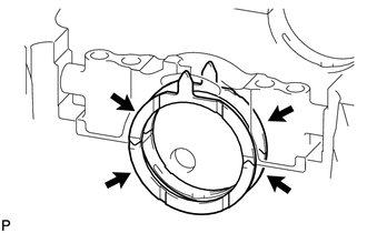
Green | 5. INSTALL CRANKSHAFT BEARING
| (a) Clean the main journal and both surfaces of the bearing. |
|
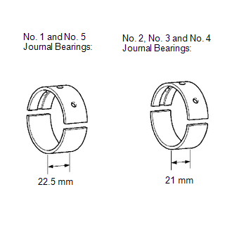
(b) Install the upper bearing. NOTICE: Main
bearings come in widths of 21 mm (0.827 in.) and 22.5 mm (0.886 in.).
Install the 22.5 mm (0.886 in.) bearings in the No. 1 and No. 5 cylinder
block journal positions with the main bearing caps. Install the 21 mm
(0.827 in.) bearings in the No. 2, No. 3 and No. 4 positions.
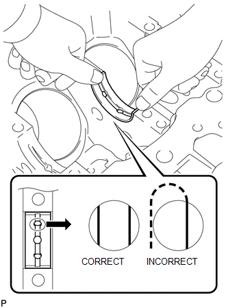
| (1) Install the upper bearing to the cylinder block as shown in the illustration.
NOTICE:
- Do not apply engine oil to the bearings and the contact surfaces.
- Both sides of the oil groove in the cylinder block should be visible
through the oil feed holes in the bearing. The amount visible on each
side of the holes should be equal.
- Do not allow coolant to come into contact with the bearing inner surface.
- If any coolant comes into contact with the bearing inner surface, replace the bearing with a new one.
| |
| (c) Install the lower bearing.
NOTICE:
- Be sure to install the selected bearing.
- Main bearings come in widths of 21 mm (0.827 in.) and 22.5 mm (0.886
in.). Install the 22.5 mm (0.886 in.) bearings in the No. 1 and No. 5
cylinder block journal positions with the main bearing caps. Install the
21 mm (0.827 in.) bearings in the No. 2, No. 3 and No. 4 positions.
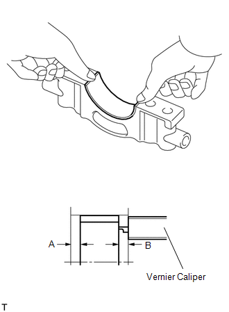
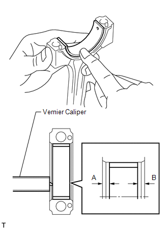
(1) Install the lower bearings to the bearing caps. (2) Using a vernier caliper, measure the distance between the bearing cap's edge and the lower bearing's edge.
Dimension A - B or B - A: 0 to 0.7 mm (0 to 0.0276 in.)
NOTICE:
- Do not apply engine oil to the bearings and the contact surfaces.
- Do not allow coolant to come into contact with the bearing inner surface.
- If any coolant comes into contact with the bearing inner surface, replace the bearing with a new one.
| |
6. INSTALL CRANKSHAFT THRUST WASHER SET
| (a) Apply engine oil to the thrust washer set. | |
(b)
Install the 4 thrust washers to the No. 3 journal position of the
cylinder block and bearing cap with the oil grooves facing outward. 7. INSTALL CRANKSHAFT
| (a) Apply engine oil to the upper bearing and lower bearing, then place the crankshaft on the cylinder block. |
|
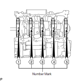
(b) Confirm the front marks and numbers of the main bearing caps, and install the bearing caps on the cylinder block.
HINT: A number is marked on each main bearing cap to indicate the installation position.
(c) Apply a light coat of engine oil on the threads and under the heads of the bearing cap bolts.
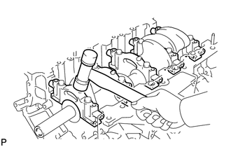
(d) Temporarily install the 10 main bearing cap bolts to the inside positions.
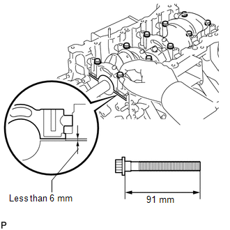
| (e)
Insert the main bearing cap by hand until the clearance between the
main bearing cap and cylinder block is less than 6 mm (0.236 in.) by
marking the 2 internal bearing cap bolts as a guide. Bolt length:
91 mm (3.58 in.) | |
| (f) Using a plastic-faced hammer, lightly tap the bearing cap to ensure a proper fit. |
|
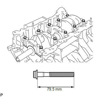
(g) Apply a light coat of engine oil to the threads and under the heads of the 10 main bearing cap bolts.
| (h) Temporarily install the 10 main bearing cap bolts to the outside positions.
Bolt length: 79.5 mm (3.13 in.) HINT: The main bearing cap bolts are tightened in 2 progressive steps. |
|
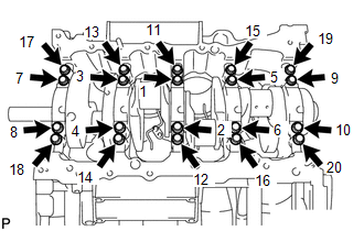
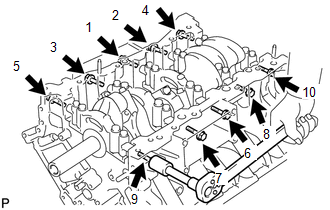
(i) Step 1: | (1) Uniformly tighten the 20 main bearing cap bolts in the sequence shown in the illustration.
Torque: for inside position : 61 N·m {622 kgf·cm, 45 ft·lbf}
for outside position : 27 N·m {275 kgf·cm, 20 ft·lbf} If any of the main bearing cap bolts do not meet the specified torque, replace it. |
|
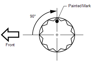
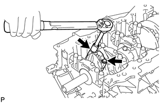
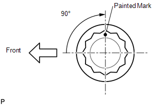
(j) Step 2: | (1) Mark the front of the bearing cap bolts with paint. |
|
(2) Tighten the bearing cap bolts another 90° in the order shown in step 1.
(3) Check that the painted marks are now at a 90° angle to the front. (k) Check that the crankshaft turns smoothly.
| (l)
Install and uniformly tighten the 10 main bearing cap bolts and 10 new
seal washers in several steps, in the sequence shown in the
illustration. Torque: 45 N·m {459 kgf·cm, 33 ft·lbf} |
|
(m) Check that the crankshaft turns smoothly. 8. INSTALL CONNECTING ROD BEARING
 (a) Clean the connecting rod's bearing contact surface, cap's bearing contact surface and both surfaces of both bearings.
(b) Install the connecting rod bearings to the connecting rods and bearing caps.
(c)
Using a vernier caliper, measure the distance between the connecting
rod's and bearing cap's edges, and each connecting rod bearing's edge. Dimension A - B or B - A:
0 to 0.7 mm (0 to 0.0276 in.)
NOTICE:
- Do not apply engine oil to the bearings and the contact surfaces.
- Do not allow coolant to come into contact with the bearing inner surface.
- If any coolant comes into contact with the bearing inner surface, replace the bearing with a new one.
9. INSTALL PISTON AND CONNECTING ROD
| (a) Apply engine oil to the cylinder walls, the pistons, and the surfaces of the connecting rod bearings. |
|
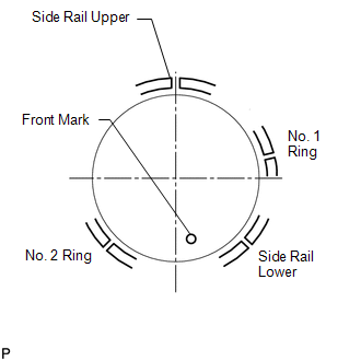
(b) Position the piston rings so that the ring ends are as shown in the illustration.
HINT: The expander ends can be placed anywhere. NOTICE: Do not align the ring ends.
| (c)
Using a hammer handle and piston ring compressor, push the correctly
numbered piston and connecting rod into the cylinder with the front mark
of the piston facing forward. | |
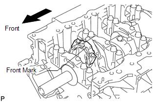
(d) Place the connecting rod cap on the connecting rod.
| (1) Match the numbered connecting rod cap with the connecting rod. |
|
(2) Check that the front mark of the connecting rod cap is facing forward.
Front Mark: |
Item | Front Mark | |
LH | Front Side | |
RH | Rear Side |
(e) Apply a light coat of engine oil to the threads and under the heads of the connecting rod cap bolts.
(f) Temporarily install the connecting rod cap bolts. HINT: The connecting rod cap bolts are tightened in 2 progressive steps.
(g) Step 1: | (1) Install and alternately tighten the bolts of the connecting rod cap in several steps.
Torque: 40 N·m {408 kgf·cm, 30 ft·lbf} | |
| (h) Step 2: (1) Mark the front side of each connecting rod cap bolt with paint.
(2) Tighten the cap bolts another 90° as shown in the illustration in the order in step 1.
(3) Check that the painted marks are now at a 90° angle to the front. |
|
(i) Check that the crankshaft turns smoothly. |