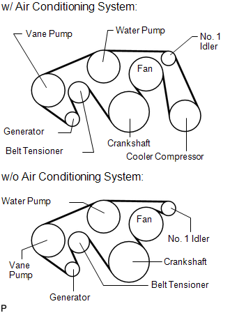
Components COMPONENTS ILLUSTRATION 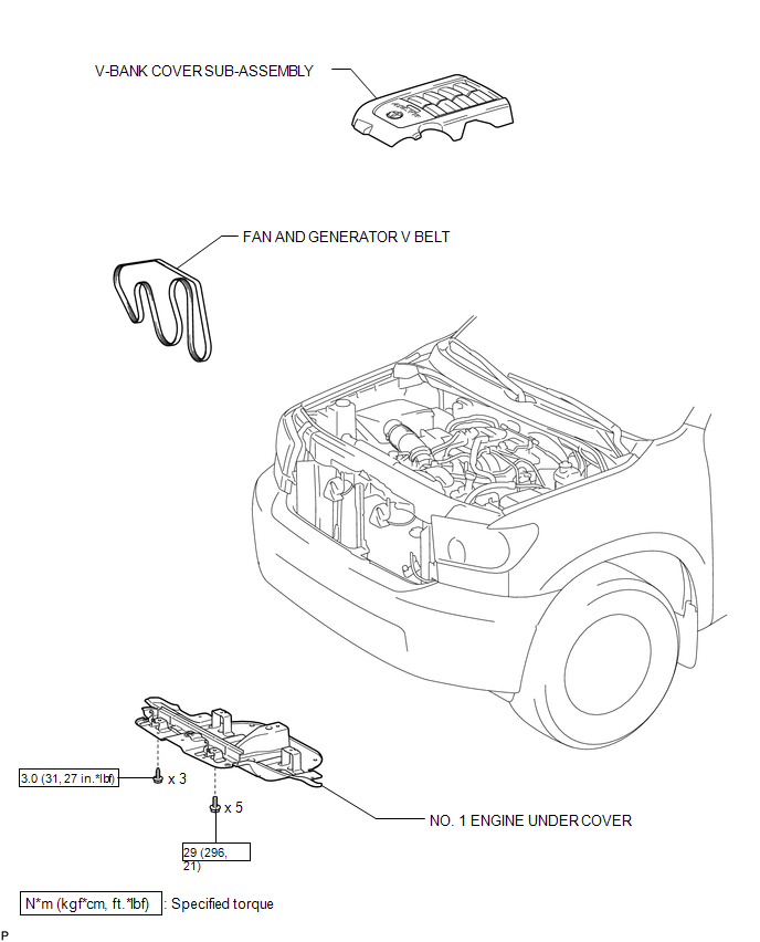 Installation INSTALLATION PROCEDURE 1. INSTALL FAN AND GENERATOR V BELT
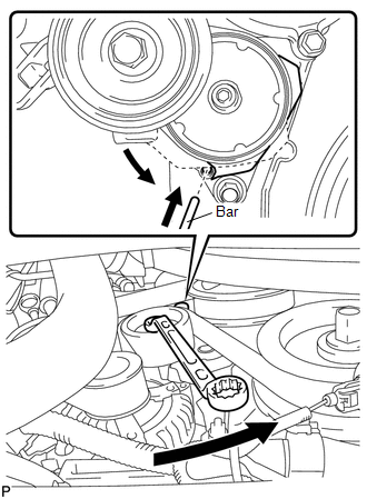
(b) While turning the belt tensioner counterclockwise, remove the pin. NOTICE: Make sure that the V belt is properly set to each pulley.
2. INSTALL NO. 1 ENGINE UNDER COVER 3. INSTALL V-BANK COVER SUB-ASSEMBLY On-vehicle Inspection ON-VEHICLE INSPECTION PROCEDURE 1. INSPECT FAN AND GENERATOR V BELT
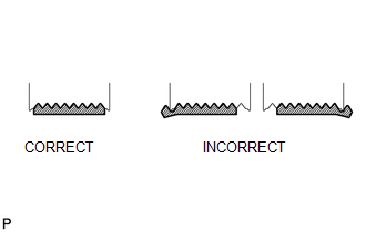
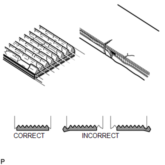
(b) Check that the belt fits properly in the ribbed grooves. HINT: Check with your hand to confirm that the belt has not slipped out of the grooves on the bottom of the pulley. If it has slipped out, replace the fan and generator V belt. Install a new fan and generator V belt correctly. 2. INSPECT V-RIBBED BELT TENSIONER ASSEMBLY (a) Check that nothing gets caught in the tensioner by turning it clockwise and counterclockwise. If the result is not as specified, replace the tensioner. Removal REMOVAL PROCEDURE 1. REMOVE V-BANK COVER SUB-ASSEMBLY 2. REMOVE NO. 1 ENGINE UNDER COVER 3. REMOVE FAN AND GENERATOR V BELT
(b) Remove the V belt. |
Toyota Tundra Service Manual > Air Conditioning System(for Automatic Air Conditioning System): Multiplex Communication Circuit (B1499/99)
DESCRIPTION This DTC outputs when CAN communication error is occurred. DTC Code DTC Detection Condition Trouble Area B1499/99 Open in CAN communication circuit CAN communication system PROCEDURE 1. CHECK FOR DTC (a) Clear the DTC (see page ). (b) Check for the DTC (see page ). Result Result Proceed ...