INSTALLATION CAUTION / NOTICE / HINT HINT: Perform
"Inspection After Repairs" after replacing the engine assembly,
cylinder head sub-assembly RH, cylinder head sub-assembly LH, No. 1
camshaft sub-assembly, No. 2 camshaft sub-assembly, No. 3 camshaft
sub-assembly, No. 4 camshaft sub-assembly, camshaft timing gear RH,
camshaft timing gear LH, camshaft timing exhaust gear RH, camshaft
timing exhaust gear LH, piston or piston ring (See page
PROCEDURE 1. REMOVE ENGINE FROM ENGINE STAND
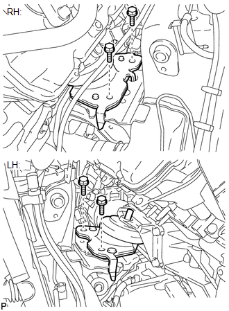
(b) Attach an engine sling device and hang the engine with a chain block. (c) Remove the bolts and engine assembly from the engine stand. 2. INSTALL ENGINE ASSEMBLY (a) Slowly lower the engine assembly into the engine compartment. NOTICE: Make sure that the engine is clear of all wiring and hoses. (b) Attach the engine mounting insulators to the vehicle.
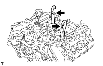
(d) Remove the 2 bolts and 2 engine hangers. 3. INSTALL DRIVE PLATE AND RING GEAR SUB-ASSEMBLY
(b) Install the crankshaft angle sensor rotor. 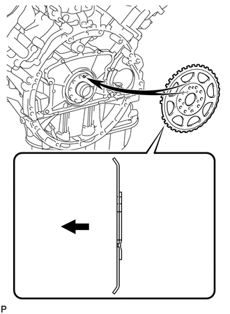
HINT:
(c) Install the drive plate and rear drive plate spacer onto the crankshaft. 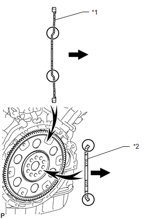
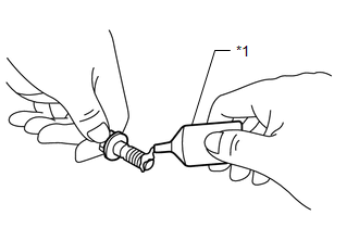
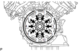
HINT: As the rear drive plate spacer and the drive plate are not reversible, be sure to install them so that they are facing in the direction shown in the illustration. (d) Install the drive plate and ring gear and bolts. HINT: The bolts are tightened in 2 progressive steps. (1) Clean the bolts and bolt holes.
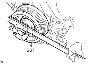
(4) Mark the top of each drive plate installation bolt with paint. (5) Step 2: Tighten the drive plate installation bolts 90° as shown in the illustration. (6) Check that the painted marks are now at a 90° angle to the top. NOTICE: Do not start the engine for at least an hour after installing the drive plate. 4. INSTALL REAR NO. 1 ENGINE MOUNTING INSULATOR (for 4WD)
5. INSTALL REAR NO. 1 ENGINE MOUNTING INSULATOR (for 2WD) 6. INSTALL AUTOMATIC TRANSMISSION ASSEMBLY (a) for 2WD: Refer to the following procedures (See page
(b) for 4WD: Refer to the following procedures (See page
7. INSTALL STARTER ASSEMBLY
8. INSTALL STARTER COVER
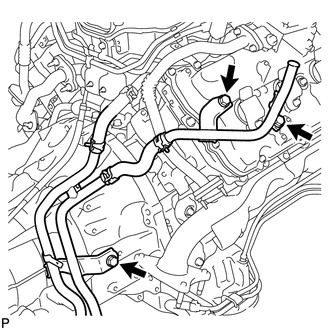
9. INSTALL EXHAUST MANIFOLD SUB-ASSEMBLY RH 10. INSTALL NO. 1 EXHAUST MANIFOLD HEAT INSULATOR 11. INSTALL EXHAUST MANIFOLD SUB-ASSEMBLY LH 12. INSTALL NO. 2 EXHAUST MANIFOLD HEAT INSULATOR 13. INSTALL NO. 1 EGR PIPE SUB-ASSEMBLY 14. INSTALL ENGINE OIL LEVEL DIPSTICK GUIDE 15. CONNECT NO. 1 WATER BY-PASS PIPE
16. INSTALL EXHAUST PIPE ASSEMBLY (a) Install the exhaust pipe assembly (See page
17. INSTALL FRONT PROPELLER SHAFT ASSEMBLY (for 4WD) (a) Install the front propeller shaft (See page
18. INSTALL PROPELLER SHAFT ASSEMBLY (a) for 2WD: Refer to the following procedures (See page
(b) for 4WD: Refer to the following procedures (See page
19. INSTALL GENERATOR ASSEMBLY
20. CONNECT VANE PUMP ASSEMBLY
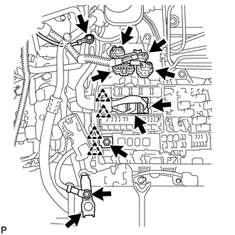
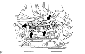
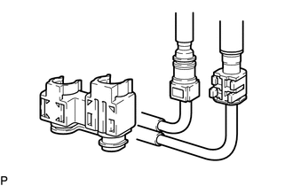
21. CONNECT COOLER COMPRESSOR ASSEMBLY 22. CONNECT WIRE HARNESS AND HOSE
(b) Install the engine wire with the nut. Then connect the 2 clips. Torque: 10 N·m {102 kgf·cm, 7 ft·lbf} (c) Connect the 4 air injection control driver connectors. (d) Install the ground wire with the bolt. Torque: 8.0 N·m {82 kgf·cm, 71 in·lbf} (e) Connect the cable to the positive (+) battery terminal. (f) Install the wire to the positive (+) battery cable with the nut. Torque: 13 N·m {133 kgf·cm, 10 ft·lbf}
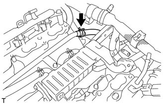
(h) Install the connector bracket with the nut. Torque: 6.0 N·m {61 kgf·cm, 53 in·lbf} (i) Connect the 2 clamps and air pump connector. (j) Connect the clamp and ground wire with the bolt. Torque: 8.0 N·m {82 kgf·cm, 71 in·lbf}
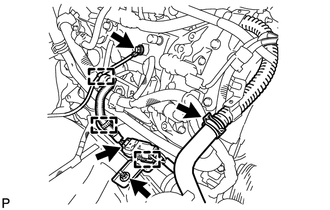
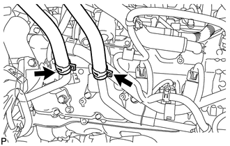
23. CONNECT NO. 2 FUEL TUBE SUB-ASSEMBLY (a) Connect the No. 2 fuel tube (See page
24. CONNECT NO. 1 FUEL PIPE SUB-ASSEMBLY
(b) Install the fuel pipe clamp. 25. INSTALL INTAKE MANIFOLD
26. INSTALL AIR TUBE SUB-ASSEMBLY LH 27. INSTALL VENTILATION HOSE ASSEMBLY 28. INSTALL EGR VALVE BRACKET 29. INSTALL EGR VALVE ASSEMBLY 30. CONNECT NO. 13 WATER BY-PASS HOSE 31. CONNECT NO. 12 WATER BY-PASS HOSE 32. INSTALL RADIATOR ASSEMBLY 33. INSTALL FAN SHROUD
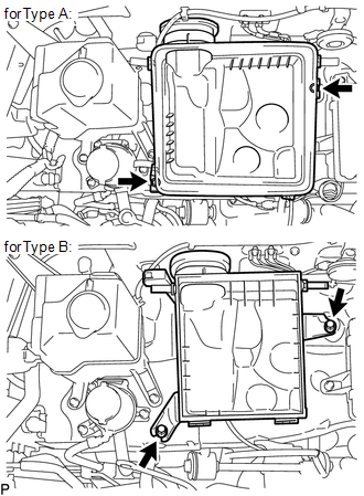
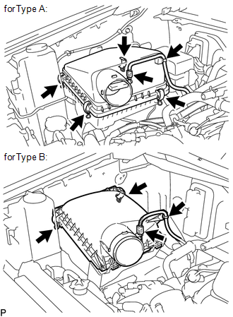
34. INSTALL FAN AND GENERATOR V BELT 35. INSTALL RADIATOR SIDE DEFLECTOR LH 36. INSTALL RADIATOR SIDE DEFLECTOR RH 37. INSTALL RADIATOR GRILLE SUB-ASSEMBLY 38. CONNECT OUTLET RADIATOR HOSE 39. INSTALL INLET RADIATOR HOSE 40. INSTALL FRONT FENDER APRON SEAL REAR LH 41. INSTALL FRONT FENDER APRON SEAL LH 42. INSTALL FRONT FENDER APRON SEAL REAR RH 43. INSTALL FRONT FENDER APRON SEAL RH 44. INSTALL COWL TOP OUTER PANEL SUB-ASSEMBLY 45. INSTALL AIR CLEANER ASSEMBLY
(b) Install the air cleaner element to the air cleaner case.
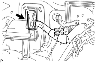
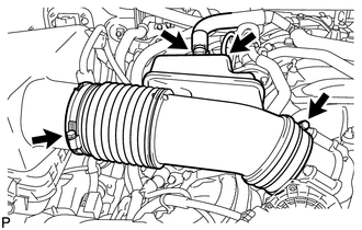
46. INSTALL AIR CLEANER HOSE ASSEMBLY
(b) Connect the ventilation hose and vacuum sensing hose. 47. ADD ENGINE OIL 48. ADD ENGINE COOLANT 49. CONNECT CABLE TO NEGATIVE BATTERY TERMINAL 50. INSPECT FOR OIL LEAK 51. INSPECT FOR COOLANT LEAK
52. INSPECT FOR EXHAUST GAS LEAK
53. INSPECT FOR FUEL LEAK
54. INSPECT SHIFT LEVER POSITION (a) for Column Shift: Refer to the following procedures (See page (b) for Floor Shift: Refer to the following procedures (See page
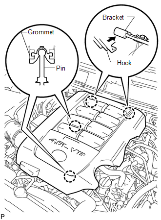
55. INSTALL V-BANK COVER SUB-ASSEMBLY
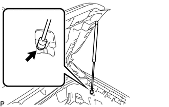
56. INSTALL HOOD SUB-ASSEMBLY
(b) Attach the lower part of the 2 hood supports to the hood support bolt ball joints. CAUTION: Install the hood support while supporting the hood by hand. (c) Attach the hood support clips. NOTICE: Check that the hood support is engaged in the ball joint and that it cannot be pulled out. 57. ADJUST HOOD SUB-ASSEMBLY 58. INSTALL NO. 1 ENGINE UNDER COVER 59. INSTALL FRONT WIPER MOTOR AND LINK ASSEMBLY (a) Install the front wiper motor and link (See page
60. INSPECT IGNITION TIMING
61. INSPECT ENGINE IDLE SPEED
62. INSPECT CO/HC
63. CHECK ENGINE OIL LEVEL
64. CHECK ENGINE COOLANT LEVEL
|
Toyota Tundra Service Manual > Audio / Video: Stereo Jack Adapter Assembly(for Column Shift Type)
ComponentsCOMPONENTS ILLUSTRATION InstallationINSTALLATION PROCEDURE 1. INSTALL NO. 1 STEREO JACK ADAPTER ASSEMBLY (a) Attach the 2 claws to install the No. 1 stereo jack adapter assembly. 2. INSTALL AIR CONDITIONING CONTROL ASSEMBLY 3. INSTALL CENTER LOWER INSTRUMENT COVER RemovalREMOVAL PROCEDURE ...

 ).
).