INSTALLATION PROCEDURE 1. INSTALL NOISE FILTER (a) RH Side: Install the noise filter to the cylinder head cover with the bolt. Torque: 10 N·m {102 kgf·cm, 7 ft·lbf} (b) LH Side: Install the noise filter to the cylinder head cover with the bolt. Torque: 10 N·m {102 kgf·cm, 7 ft·lbf} 2. INSTALL IGNITION COIL ASSEMBLY (a) Install the 8 ignition coils with the 8 bolts. Torque: 10 N·m {102 kgf·cm, 7 ft·lbf} 3. INSTALL KNOCK SENSOR 4. INSTALL NO. 11 WATER BY-PASS HOSE
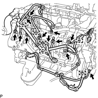
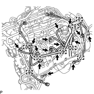
5. INSTALL ENGINE WIRE 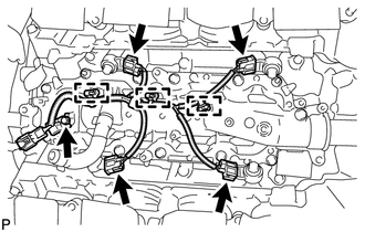 (a) Connect the 3 clamps and 4 knock sensor connectors to install the engine wire. 6. INSTALL NO. 1 ENGINE COVER
7. INSTALL NO. 2 ENGINE COVER
8. INSTALL SEPARATOR CASE 9. INSTALL NO. 1 IDLER PULLEY SUB-ASSEMBLY 10. INSTALL WATER PUMP PULLEY 11. INSTALL FRONT WATER BY-PASS JOINT 12. INSTALL WATER INLET HOUSING 13. INSTALL WATER BY-PASS PIPE SUB-ASSEMBLY 14. INSTALL AIR TUBE SUB-ASSEMBLY RH 15. INSTALL NO. 1 WATER BY-PASS HOSE 16. INSTALL NO. 3 ENGINE COVER 17. INSTALL NO. 4 ENGINE COVER 18. INSTALL OIL PRESSURE SENDER GAUGE ASSEMBLY 19. INSTALL FUEL DELIVERY PIPE SUB-ASSEMBLY RH 20. INSTALL FUEL DELIVERY PIPE SUB-ASSEMBLY LH 21. INSTALL FRONT NO. 1 ENGINE MOUNTING BRACKET LH  (a) Install the mounting bracket with the 4 bolts. Torque: 35 N·m {357 kgf·cm, 26 ft·lbf} 22. INSTALL FRONT NO. 1 ENGINE MOUNTING BRACKET RH 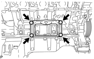 (a) Install the mounting bracket with the 4 bolts. Torque: 35 N·m {357 kgf·cm, 26 ft·lbf} 23. INSTALL FRONT ENGINE MOUNTING INSULATOR RH
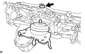
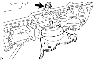
24. INSTALL FRONT ENGINE MOUNTING INSULATOR LH
25. INSTALL CYLINDER BLOCK WATER DRAIN COCK SUB-ASSEMBLY 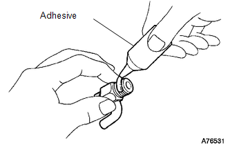 (a) Apply adhesive to 2 or 3 threads of the drain cocks. Adhesive: Toyota Genuine Adhesive 1344, Three Bond 1344 or equivalent 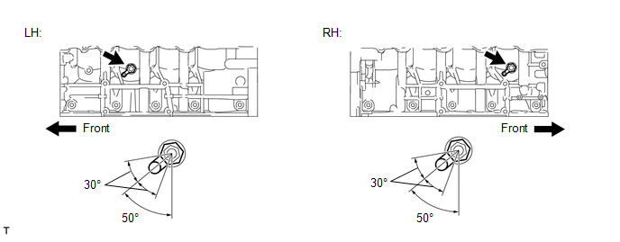 (b) Install the water drain cocks. Torque: 30 N·m {306 kgf·cm, 22 ft·lbf} (c) Tighten the drain cocks up to an additional 360° so that the drain cock pipes are within the range shown in the illustration. NOTICE:
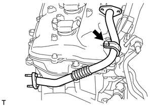
(d) Install the water drain cock plugs to the water drain cocks. Torque: 13 N·m {130 kgf·cm, 9 ft·lbf} 26. INSTALL EGR COOLER ASSEMBLY 27. CONNECT NO. 11 WATER BY-PASS HOSE 28. INSTALL NO. 8 WATER BY-PASS HOSE
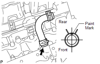
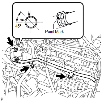
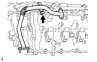
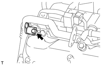
29. INSTALL NO. 3 WATER BY-PASS PIPE SUB-ASSEMBLY
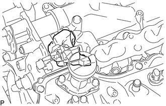
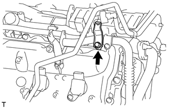
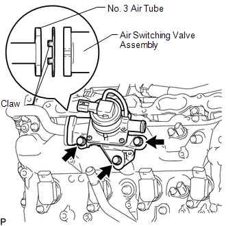
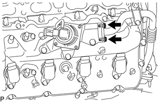
30. INSTALL NO. 3 AIR TUBE
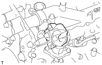
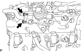
31. INSTALL NO. 4 AIR TUBE
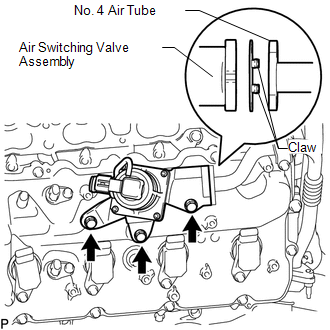
32. INSTALL AIR SWITCHING VALVE ASSEMBLY (for Bank 2)
33. INSTALL AIR SWITCHING VALVE ASSEMBLY (for Bank 1)
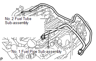
34. INSTALL NO. 2 FUEL TUBE SUB-ASSEMBLY
35. INSTALL NO. 1 FUEL PIPE SUB-ASSEMBLY (a) Install the No. 1 fuel pipe (See page
36. INSTALL ENGINE WIRE 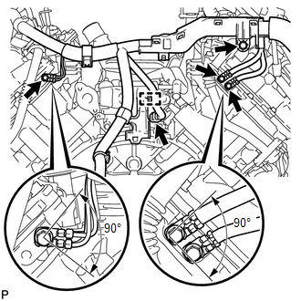 (a) Engine Rear Side: (1) Install the 4 bolts. Torque: 8.4 N·m {86 kgf·cm, 74 in·lbf} (2) Connect the clamp and connector.
|
Toyota Tundra Service Manual > Blind Spot Monitor System: Short to GND in Outer Mirror Indicator(Master) (C1AB2)
DESCRIPTION This DTC is stored when the blind spot monitor sensor RH detects a short to ground in the outer rear view mirror indicator RH. DTC No. DTC Detection Condition Trouble Area C1AB2 Both of the following conditions are met: The blind spot monitor system is on The current that is sent from th ...