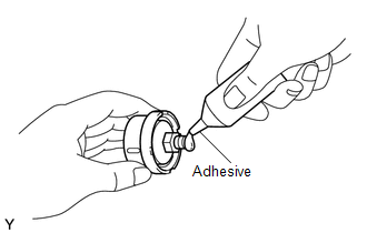
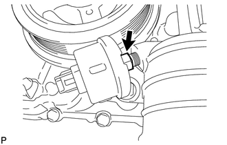
Components COMPONENTS ILLUSTRATION 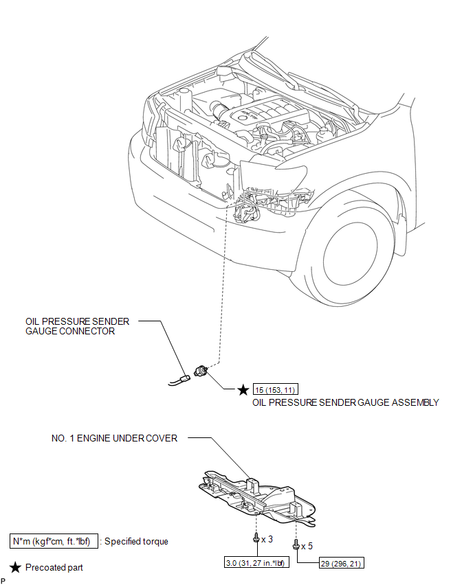 Installation INSTALLATION PROCEDURE 1. INSTALL OIL PRESSURE SENDER GAUGE ASSEMBLY
2. INSPECT ENGINE OIL LEVEL 3. INSPECT FOR OIL LEAK 4. INSTALL NO. 1 ENGINE UNDER COVER On-vehicle Inspection ON-VEHICLE INSPECTION PROCEDURE 1. INSPECT OIL PRESSURE SENDER GAUGE ASSEMBLY
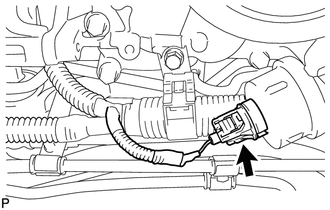
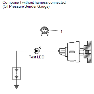
(b) Apply battery positive (+) voltage to the sender gauge terminal through a test LED. (c) Check that the LED does not illuminate when the engine is stopped. (d) Check that the LED flashes when the engine is running. The number of flashes varies with engine speed. If the operation is not as specified, replace the oil pressure sender gauge assembly. Removal REMOVAL PROCEDURE 1. REMOVE NO. 1 ENGINE UNDER COVER 2. REMOVE OIL PRESSURE SENDER GAUGE ASSEMBLY
|
Toyota Tundra Service Manual > Air Conditioning System(for Automatic Air Conditioning System): Solar Sensor Circuit (Driver Side) (B1424/24)
DESCRIPTION The solar sensor, which is installed on the upper side of the instrument panel, detects sunlight and controls the air conditioning in AUTO mode. The output current from the solar sensor varies according to the amount of sunlight. When the sunlight increases, the output current increases. ...