REMOVAL PROCEDURE 1. PRECAUTION NOTICE: After
turning the ignition switch off, waiting time may be required before
disconnecting the cable from the battery terminal. Therefore, make sure
to read the disconnecting the cable from the battery terminal notice
before proceeding with work (See page 2. DISCONNECT CABLE FROM NEGATIVE BATTERY TERMINAL 3. REMOVE STEERING COLUMN ASSEMBLY (a) for Manual Tilt: (See page
(b) for Manual Tilt and Manual Telescopic Steering Column: (See page
4. REMOVE UPPER STEERING COLUMN WITH SWITCH BRACKET ASSEMBLY (for Manual Tilt) 5. REMOVE UPPER STEERING COLUMN WITH SWITCH BRACKET ASSEMBLY (for Manual Tilt and Manual Telescopic Steering Column) 6. REMOVE IGNITION SWITCH ASSEMBLY 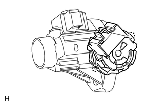 (a) Detach the 2 claws and remove the ignition switch from the steering lock. |
Toyota Tundra Service Manual > Throttle Body: Installation
INSTALLATION CAUTION / NOTICE / HINT HINT: Perform "Inspection After Repairs" after replacing the throttle body assembly (See page ). PROCEDURE 1. INSTALL THROTTLE BODY ASSEMBLY HINT: Perform "Inspection After Repairs" after replacing the throttle body assembly (See page ). (a) Install the No. 4 wat ...


