DESCRIPTION Refer to DTC P0711 (See page
 ).
). |
DTC Code | DTC Detection Condition |
Trouble Area | | P0712 |
ATF temperature sensor resistance is below 79 Ω for 0.5 sec. or more (1-trip detection logic). |
- Short in ATF temperature sensor circuit
- ATF temperature sensor
- ECM
| | P0713 |
ATF
temperature sensor resistance is higher than 156 kΩ for 0.5 sec. or
more and either of the following conditions is met (1-trip detection
logic): (A) 338 sec. or more have elapsed after the
engine start when the engine coolant temperature or intake air
temperature is -29.375°C (-20.875°F) or less. (B) 10
sec. or more have elapsed after the engine start when the engine
coolant temperature and intake air temperature are higher than -29.375°C
(-20.875°F). |
- Open in ATF temperature sensor circuit
- ATF temperature sensor
- ECM
| MONITOR DESCRIPTION
The
ATF temperature sensor converts the ATF temperature to an electrical
resistance value. Based on the resistance, the ECM determines the ATF
temperature and detects an open or short in the ATF temperature sensor
circuit. If the resistance value of the ATF temperature sensor is below
79 Ω*1 or higher than 156 kΩ*2, the ECM interprets this as a fault in
the ATF temperature sensor or wiring. The ECM will illuminate the MIL
and store the DTC.
HINT:
- *1: 150°C (302°F) or higher is indicated regardless of the actual ATF temperature.
- *2: -40°C (-40°F) is indicated regardless of the actual ATF temperature.
- The ATF temperature can be checked on the Techstream display.
MONITOR STRATEGY |
Related DTCs | P0712: ATF temperature sensor/Range check (Low voltage)
P0713: ATF temperature sensor/Range check (High voltage) | |
Required sensors/Components | ATF temperature sensor | |
Frequency of operation | Continuous | |
Duration | 0.5 seconds | |
MIL operation | Immediately | |
Sequence of operation | None | TYPICAL ENABLING CONDITIONS P0712: Range check (Low voltage)
-
|
The monitor will run whenever the following DTCs are not present
|
None |
|
Battery voltage |
8 V or higher |
|
Ignition switch |
ON |
|
Starter |
OFF |
P0713: Range check (High voltage)
- Either condition is met: Condition (A) or (B)
Condition (A)
-
|
The monitor will run whenever the following DTCs are not present
|
P0115, P0117, P0118 (ECT (Engine Coolant Temperature) sensor circuit)
P00AC, P00AD, P0110, P0112, P0113 (IAT (Intake Air Temperature) sensor circuit)
|
|
Engine coolant temperature or intake air temperature at engine start
|
-29.375°C (-20.875°F) or less |
|
Time after engine start |
338 seconds or more |
|
Battery voltage |
8 V or higher |
|
Ignition switch |
ON |
|
Starter |
OFF |
Condition (B)
-
|
The monitor will run whenever the following DTCs are not present
|
P0115, P0117, P0118 (ECT (Engine Coolant Temperature) sensor circuit)
P00AC, P00AD, P0110, P0112, P0113 (IAT (Intake Air Temperature) sensor circuit)
|
|
Engine coolant temperature and intake air temperature at engine start
|
Higher than -29.375°C (-20.875°F) |
|
Time after engine start |
10 seconds or more |
|
Battery voltage |
8 V or higher |
|
Ignition switch |
ON |
|
Starter |
OFF |
TYPICAL MALFUNCTION THRESHOLDS P0712: Range check (Low voltage) |
ATF temperature sensor voltage | Below 0.14 V (Higher than 164°C (327.2°F)) | P0713: Range check (High voltage) |
ATF temperature sensor voltage | Higher than 4.91 V (Below -48°C (-54.4°F)) | COMPONENT OPERATING RANGE |
ATF temperature sensor voltage | 0.14 to 4.91 V | WIRING DIAGRAM
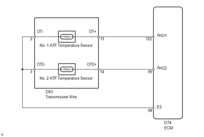 CAUTION / NOTICE / HINT
NOTICE: Perform the universal trip to clear permanent DTCs (See page
). 1. DATA LIST HINT: Using
the Techstream to read the Data List allows the values or states of
switches, sensors, actuators and other items to be read without removing
any parts. This non-intrusive inspection can be very useful because
intermittent conditions or signals may be discovered before parts or
wiring is disturbed. Reading the Data List information early in
troubleshooting is one way to save diagnostic time. NOTICE: In
the table below, the values listed under "Normal Condition" are
reference values. Do not depend solely on these reference values when
deciding whether a part is faulty or not. (a) Warm up the engine. (b) Turn the ignition switch off.
(c) Connect the Techstream to the DLC3. (d) Turn the ignition switch to ON.
(e) Turn the Techstream on. (f) Enter the following menus: Powertrain / Engine and ECT / Data List.
(g) According to the display on the Techstream, read the Data List. Engine and ECT |
Tester Display | Measurement Item/Range |
Normal Condition | Diagnostic Note | |
A/T Oil Temperature 1 | No. 1 ATF temperature sensor value/
Min.: -40°C (-40°F) Max.: 150°C (302°F) |
- After stall test: Approximately 80°C (176°F)
- Equal to ambient temperature when engine cold
| If the value is -40°C (-40°F) or 150°C (302°F), the No. 1 ATF temperature sensor circuit is open or shorted. |
HINT: When DTC P0712 is output and the Techstream output is 150°C (302°F) or more, there is a short circuit.
When DTC P0713 is output and the Techstream output is -40°C (-40°F), there is an open circuit.
Check the temperature displayed on the tester in order to check if a malfunction exists. |
Temperature Displayed | Malfunction | |
-40°C (-40°F) | Open circuit | |
150°C (302°F) or more |
Short circuit | If
a circuit related to the ATF temperature sensor becomes open, P0713 is
immediately stored (in 0.5 seconds). When P0713 is stored, P0711 cannot
be stored. It is not necessary to inspect the circuit when P0711 is stored. PROCEDURE
| 1. |
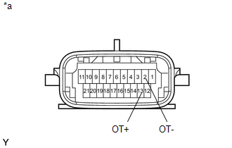
INSPECT TRANSMISSION WIRE (NO. 1 ATF TEMPERATURE SENSOR) |
| (a) Disconnect the D83 transmission wire connector. | |
(b) Measure the resistance according to the value(s) in the table below.
Standard Resistance: |
Tester Connection | Condition |
Specified Condition | | 2 (OT-) - 13 (OT+) |
Always | 79 Ω to 156 kΩ | |
2 (OT-) - Body ground |
Always | 10 kΩ or higher | |
13 (OT+) - Body ground |
Always | 10 kΩ or higher |
HINT: If
the resistance is out of the specified range at any of the ATF
temperatures shown in the table below, the driveability of the vehicle
may decrease. Standard Resistance: |
ATF Temperature | Specified Condition | |
10°C (50°F) | 5 to 8 kΩ | |
25°C (77°F) | 2.5 to 4.5 kΩ | |
110°C (230°F) | 0.22 to 0.28 kΩ | Text in Illustration |
*a | Component without harness connected
(Transmission Wire) |
| NG |
 | REPAIR OR REPLACE TRANSMISSION WIRE (NO. 1 ATF TEMPERATURE SENSOR) |
|
OK |
 | |
| 2. |
CHECK HARNESS AND CONNECTOR (TRANSMISSION WIRE - ECM) |
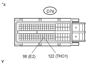
| (a) Disconnect the D74 ECM connector. | |
(b) Measure the resistance according to the value(s) in the table below.
Standard Resistance: |
Tester Connection | Condition |
Specified Condition | | D74-122 (THO1) - D74-98 (E2) |
Always | 79 Ω to 156 kΩ | |
D74-122 (THO1) - Body ground |
Always | 10 kΩ or higher | |
D74-98 (E2) - Body ground |
Always | 10 kΩ or higher | Text in Illustration |
*a | Front view of wire harness connector
(to ECM) |
| OK |
| REPLACE ECM |
| NG |
| REPAIR OR REPLACE HARNESS OR CONNECTOR | |